Think about it like this: what if you could get the performance of a 500mm compacted clay layer using just 8 mm thickness material for hydraulic protection? And it is not a theoretical advantage. It’s what essentially geosynthetic clay liners give at the site.
For civil engineers and geosynthetic facilities, the challenge keeps on repeating: getting reliable contamination barriers, and that too for years, without the logistical nightmare of transporting and compacting thousands of cubic meters of clay. Compacted clay liners (CCLs) necessitate some heavy machines, absolute moisture control, a hell of a lot of labor, and perhaps perfect weather primitives: one failed compaction, or one misinterpretation in the test, might delay the job by weeks.
Geosynthetic clay liners provide a consistent and faster-installing manufactured alternative that, being often less expensive in total project costs, are designed with a more stabilizing hold. The global GCL market itself crossed $523.2 million in 2025, expanding at a CAGR of 5.1 percent, as more engineering teams come to grips with these benefits.
The guide is aimed at those who need to mention, choose, and install geosynthetic clay liners in landfill containment as well as mining, use in water management, and environmental protection.
What you will learn:
- How GCLs work and what makes them different from geomembranes
- The five types of GCLs and when to use each
- Complete comparison: GCL vs compacted clay vs geomembrane
- Engineering specifications and ASTM standards
- Installation best practices from site preparation to quality control
What Is a Geosynthetic Clay Liner?
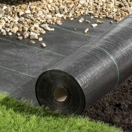
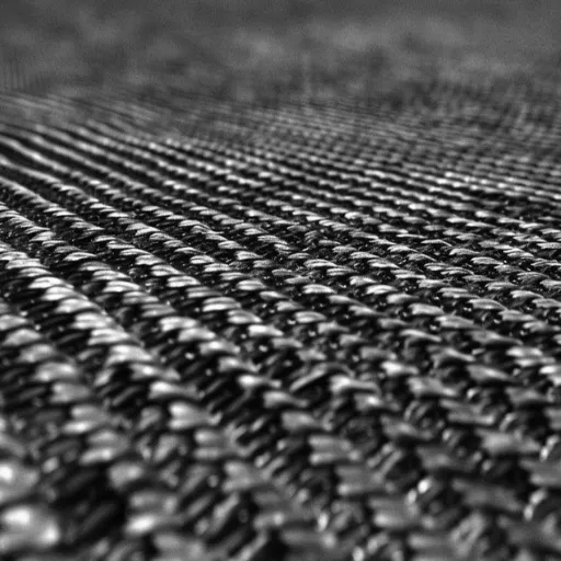
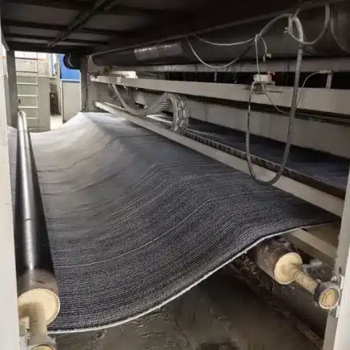
A geosynthetic clay liners is a factory-manufactured, compacted hydraulic barrier made of granular sodium bentonite sandwiched between geotextile layers, which, after hydration, allows the bentonite to swell and create a dense and impervious barrier against liquid migration.
Composition and Structure
Standard Geosynthetic Clay Liners comprises three integral properties:
Sodium Bentonite Clay Core
Barrier active ingredient is natural sodium bentonite, generally applied at rates of 4,000-5,500 grams per square meter. Sodium bentonite is made of very unique crystal structures, allowing water absorption for expansion up to 10-17 times the original volume; the swelling typically creates an impermeable barrier seal for effective GCL operation.
Geotextile Encapsulation Layers
Bentonite is wedged between a couple of geotextile layers for segregating the soil and forming the basis of the structure.
- Top layer: Nonwoven is highly used for filtration and protection.
- Bottom layer: Highly preferred are woven geotextiles for strength and dimensional stability.
Reinforcement System
The geotextile being bonded together by either of the two methods is:
- Needle-punching: The geotextile fibers with bentonite are combed and entangled after they are physically poked with needle-like barbed needles to make the composite a reinforced matrix.
- Stitch-bonding: Thread stitching is the method of stitching two layers together (non-critical applications are mostly used).
How GCLs Work: The Self-Healing Mechanism
Water molecules absorb the detritus as they enter the water through the gaps in the clay, which contains the sodium ions. In doing this, the platelet-like structure swells. Consequently, such an increase in the size of mineral particles can block voids, resulting in the birth of a gel-type barrier with hydraulic conductivity of ≤1×10⁻⁹ meters per second, which is almost or better than a well-compacted clay liner.
The main characteristic of GCLs is self-healing capabilities, as opposed to rigid barriers such as geomembranes. Tiny punctures or tears in the geotextile do not compromise the liner as swelling bentonite seals off around the damaged portion. This feature makes GCLs very reliable in real-world use, especially since the little damage during installation is hard to prevent.
Types of Geosynthetic Clay Liners
Not all GCLs perform the same. Understanding the five main types helps you select the right product for your specific application.
Standard Needle-Punched GCL
This is the most common GCL configuration, suitable for the majority of containment applications.
Structure: Bentonite core between woven and nonwoven geotextiles, mechanically bonded through needle-punching
Best for: Landfill base liners, pond sealing, general containment
Key advantage: Excellent shear strength and internal friction properties
Typical specifications: 4,000–5,000 g/m² bentonite mass, peel strength ≥65 N/m
Needle-punched GCLs offer the greatest equilibrium among cost, performance, and ease of installation. The specificity of needle-punching is that the process creates three-dimensional fiber to reinforce the bentonite, which will prevent the whole mass of bentonite from shifting under load.
Stitch-Bonded GCL
Stitch-bonded GCLs use thread stitching rather than needle-punching to bond the geotextile layers.
Structure: Bentonite core with stitched seams at regular intervals
Best for: Applications requiring high internal shear resistance
Key advantage: Lower cost than needle-punched alternatives
Limitation: Reduced uniformity and potential for bentonite migration at stitch lines
Stitch-bonded GCLs have declined in popularity for critical containment applications because needle-punched products offer superior performance at comparable cost. However, they remain available for projects with less stringent requirements.
Coated/Multicomponent GCL
Polymerization will go beyond the standing GCL facial side.
Structure: Standard geosynthetic clay liners, needle-punch construction, further accompanied by a geomembrane or polymer bonneting.
Best For: Applications needing better chemical resistance or reduced gas permeability
Key Advantage: It unites the self-healing properties of bentonite with the resistance to alkali of a geomembrane.
Common Coatings: HDPE, LLDPE, or flexible polyolefin (FPO) membranes
An additional chemical-resistant finish is produced for areas affected by bentonite; thus, bentonite is needed to ensure that self-healing features are rendered to the areas damaged in that part of the coating.
Geomembrane-Backed GCL (Composite)
Composite GCLs laminate a full geomembrane to the GCL structure, creating a two-layer barrier system in a single product.
Structure: Needle-punched GCL factory-bonded to HDPE, LLDPE, or PVC geomembrane
Best for: Landfill caps, secondary containment, applications requiring redundant barriers
Key advantage: Combines GCL self-healing with geomembrane chemical resistance in one installation step
Typical configuration: 1.5–2.0mm geomembrane bonded to 4,000–5,000 g/m² GCL
Composite GCLs eliminate the need for separate GCL and geomembrane installations, reducing labor and potential installation errors. They are increasingly specified for landfill caps where differential settlement could stress a standalone geomembrane.
Polymer-Enhanced GCL
Through the addition of polymer, the bentonite in a GCL is aided to perform well under aggressive chemical environmental conditions.
Structure: Standard GCL construction comprising polymer-treated bentonite
Best for: Heap leach mining applications, high ionic-strength leachate for industrial containment
Key Advantage: Retains low hydraulic conductivity even in exposure to chemicals, hastening the degradation of natural bentonite
Enhancement types: A combination of sodium-bentonite and proprietary polymers
The normal sodium bentonite will experience an increase in permeability with exposure to a high concentration of certain cations (calcium and magnesium) or to extreme pH conditions. Polymer-formulated improvements resist these effects, which is why they are extremely useful in mining and industrial applications.
GCL vs Alternative Liner Systems
Selecting the right liner requires understanding how GCLs compare to traditional alternatives. Each system has distinct advantages for specific applications.
GCL vs Compacted Clay Liner (CCL)
Compacted clay liners have been the traditional standard for containment applications, but GCLs offer compelling advantages.
| Factor | GCL | Compacted Clay Liner |
|---|---|---|
| Thickness | 8–10mm | 500–1,000mm |
| Hydraulic conductivity | ≤1×10⁻⁹ m/s | 1×10⁻⁹ to 1×10⁻⁷ m/s |
| Coverage per truckload | ~6,000 m² | ~40 m² |
| Installation speed | 2,000–4,000 m²/day | 200–500 m²/day |
| Weather sensitivity | Low (install in light rain) | High (moisture control critical) |
| Quality control | Factory-controlled | Field-dependent |
| Self-healing capability | Yes | No |
When GCLs outperform CCLs:
- Remote sites where clay import is expensive or impractical
- Projects with tight schedules
- Sloped applications where CCL compaction is difficult
- Applications requiring self-healing for long-term reliability
When CCLs may still be preferred:
- Projects requiring extremely thick barriers for structural reasons
- Sites with readily available suitable clay and low transport costs
- Applications where GCL polymers could be chemically incompatible
GCL vs HDPE Geomembrane
GCLs and geomembranes serve different primary functions but are often used in conjunction with one another.
Barrier Mechanism
- GCL: Active barrier, but bentonite swelling; self-healing; improves performance when hydrated
- Geomembrane: Passive barrier with material imperviousness; susceptible to puncture and tear
Chemical Resistance
- GCL: Moderate; basic bentonite susceptible to harsh chemicals; polymer-enhanced systems available
- Geomembrane: Excellent; ample chemical resistance of HDPE across a wide range of pHs
Installation Characteristics
- GCL: Flexible-undergoes subgrade irregularities, overlaps without welding
- Geomembrane: Precise welding is necessary; it sensitively creates wrinkles and bridging
Cost Considerations
- GCL: Lower material cost, fast install, minimal equipment requirements
- Geomembrane: Higher material costs, specialized welding equipment, and certified operators
When to Use Composite Systems (GCL + Geomembrane)
The most robust containment designs often combine both technologies:
Typical composite configuration:
- Lower layer: GCL for self-healing backup and leak location
- Upper layer: HDPE geomembrane for primary chemical resistance
- Protection layer: Geotextile between the geomembrane and the cover soil
Benefits of composite systems:
- Redundant protection: If the geomembrane is compromised, the GCL provides secondary containment
- Leak detection: The GCL layer can be designed to channel leaks to collection systems
- Chemical protection: Geomembrane handles aggressive chemicals; GCL provides self-healing backup
- Installation efficiency: Composite GCLs (factory-bonded) eliminate separate installation steps
Composite systems are now standard for municipal solid waste landfills and hazardous waste containment in many jurisdictions.
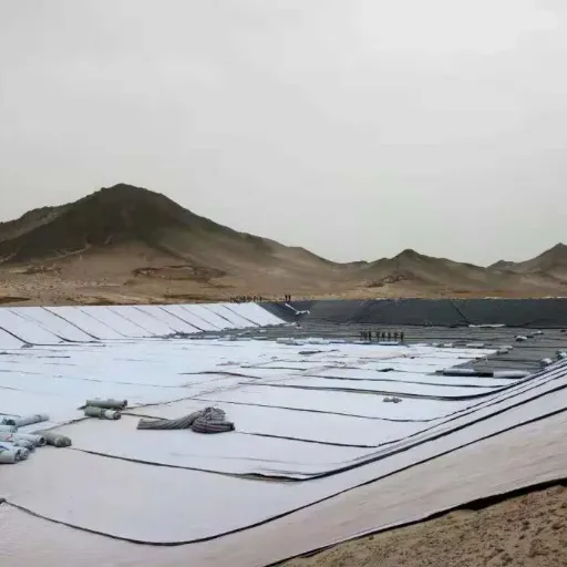
Key Applications for Geosynthetic Clay Liners
GCLs serve critical functions across multiple industries. Understanding typical applications helps engineers specify appropriate products.
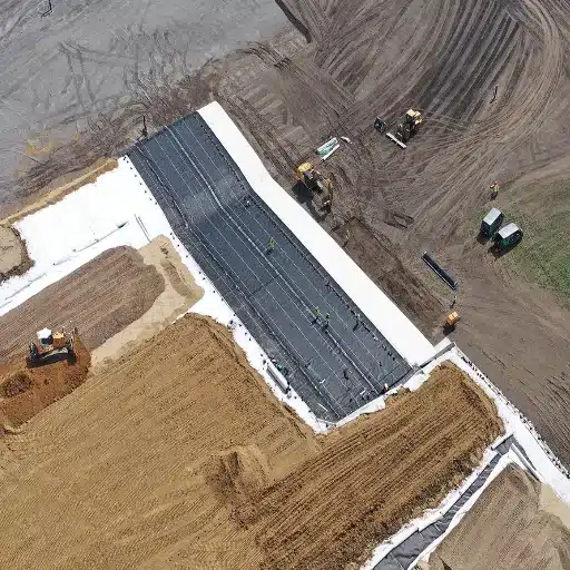
Landfill Base Liners and Caps
Landfills represent the largest GCL application segment, accounting for 41.2% of global demand.
Base Liner Applications
- Primary liner in single-liner systems
- Secondary liner in double-liner composite systems
- Leak detection layer between geomembranes
Cap Applications
- Final cover systems to prevent water infiltration
- Closure caps that accommodate settlement
- Erosion control on finished slopes
GCLs excel in landfill caps because their flexibility accommodates differential settlement that would crack rigid geomembranes. The self-healing property provides long-term reliability even if the cap is damaged by waste settlement or root intrusion.
Mining: Tailings and Heap Leach Pads
Mining operations use GCLs in some of their most demanding applications.
Tailings Storage Facilities
GCLs provide base liners for tailings impoundments where long-term containment of process water and fine particulates is essential. Polymer-enhanced GCLs are typically specified to resist the chemical characteristics of specific ore processing solutions.
Heap Leach Pads
Heap leach mining for copper, gold, and other metals requires liners that can withstand:
- Aggressive chemical solutions (sulfuric acid, cyanide)
- Heavy loading from ore piles
- Extreme temperature variations
Polymer-enhanced GCLs combined with HDPE geomembranes provide the chemical resistance and mechanical protection required for these applications.
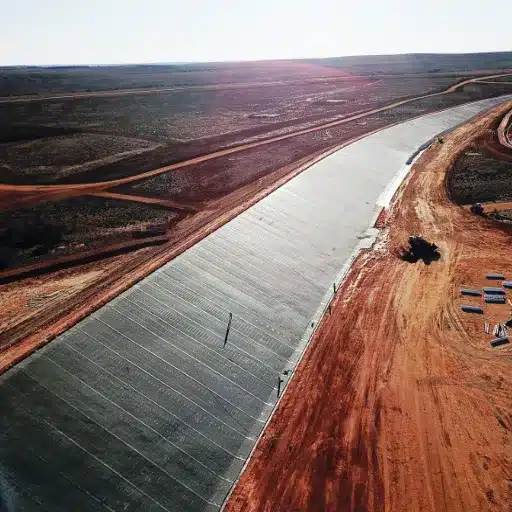
Water Containment: Ponds, Canals, and Reservoirs
Water conservation and management projects benefit from GCL’s performance characteristics.
Irrigation Canals
The E-Canal project in Australia demonstrated GCL’s effectiveness for water conservation. GCL-lined canals reduced seepage losses by over 90% compared to unlined channels, delivering water savings that paid for the liner installation within three years.
Reservoirs and Ponds
GCLs provide cost-effective lining for:
- Fire protection water storage ponds
- Agricultural irrigation reservoirs
- Aquaculture facilities
- Stormwater detention basins
The rapid installation and minimal equipment requirements make GCLs particularly attractive for remote water storage projects.
Environmental Remediation
Contaminated site remediation often requires temporary or permanent containment barriers.
Cutoff Walls
GCL panels installed in vertical trenches create barriers to groundwater flow, containing contaminant plumes. The self-healing property ensures barrier continuity even if panels shift during installation.
Capping Contaminated Soils
GCL caps prevent infiltration through contaminated soil caps, reducing leachate generation and protecting groundwater. The thin profile minimizes cap thickness while meeting regulatory requirements.
Secondary Containment
Industrial facilities use GCLs for secondary containment around:
- Above-ground storage tanks
- Chemical processing areas
- Loading and unloading facilities
- Transformer stations
GCLs provide reliable secondary containment at a lower cost than concrete or compacted clay alternatives, with faster installation that minimizes facility downtime.
Engineering Specifications and Standards
Proper specification ensures GCL performance meets project requirements. Understanding key properties and applicable standards helps engineers write effective specifications.
Critical Performance Properties
Bentonite Mass Per Unit Area
The mass of bentonite per square meter directly affects hydraulic performance.
- Standard range: 4,000–5,500 g/m²
- Minimum specification: ≥3,700 g/m² (ASTM D5993)
- Higher mass: Improved hydraulic conductivity and self-healing capacity
Peel Strength
Peel strength measures the bond between geotextile layers and indicates installation durability.
- Minimum specification: ≥65 N/m (ASTM D6496)
- Typical needle-punched GCL: 80–150 N/m
- Critical applications: Specify minimum peel strength requirements
Hydraulic Conductivity
The fundamental performance metric for any liner.
- Maximum specification: ≤5×10⁻¹¹ m/s (ASTM D5084)
- Typical performance: 1×10⁻¹¹ to 1×10⁻¹² m/s
- Test conditions: Deionized water, 35 kPa effective stress
Internal Shear Strength
Internal shear strength is critical for sloped applications.
- Peak shear strength: 20–50 kPa, depending on normal stress
- Large-scale testing: ASTM D6243 for design values
- Residual strength: Consider for high-strain applications
ASTM Standards Reference
The following ASTM standards govern GCL testing and specification:
D5890: Standard Test Method for Swell Index of Clay Mineral Component of Geosynthetic Clay Liners
- Measures bentonite swelling capacity
- Minimum requirement: ≥24 mL/2g for sodium bentonite
D5993: Standard Test Method for Measuring Mass Per Unit of Geosynthetic Clay Liners
- Confirms bentonite mass meets specification
- The average of five samples must meet the minimum
D5084: Standard Test Methods for Measurement of Hydraulic Conductivity of Saturated Porous Materials
- Determines permeability under specified conditions
- Test using site-specific permeants for critical applications
D6496: Standard Test Method for Measuring Peel Strength of Geosynthetic Clay Liners
- Evaluates bond strength between geotextile layers
- Conducted at a 300 mm/min separation rate
D6102: Standard Guide for Installation of Geosynthetic Clay Liners
- Provides installation best practices
- Reference for specification writing and quality control
D6243: Standard Test Method for Determining the Internal and Interface Shear Strength of Geosynthetic Clay Liners by the Direct Shear Method
- Required for sloped applications
- Perform with site-specific materials and conditions
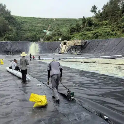
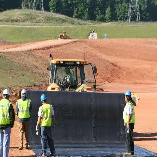
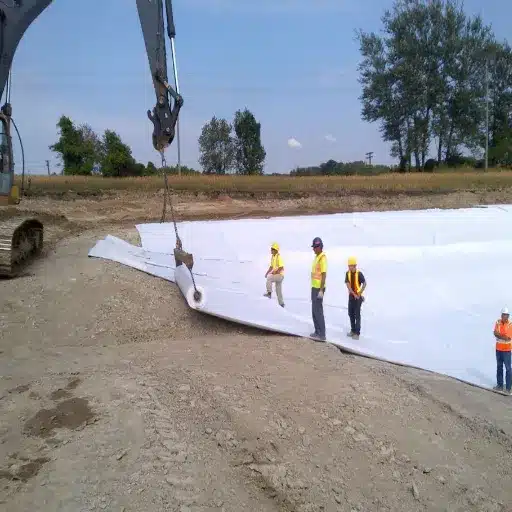
Installation Best Practices

Even the highest-quality GCL will fail if improperly installed. Following proven installation procedures ensures liner performance.
Subgrade Preparation Requirements
Surface Quality
The subgrade must be:
- Free of rocks, roots, and debris larger than 20mm
- Compacted to ≥90% standard Proctor density
- Smooth with no sudden elevation changes
- Properly sloped for drainage
Acceptable subgrade materials:
- Compacted soil
- Compacted sand or gravel
- Geotextile-covered rough surfaces
- Geomembrane (for composite systems)
Unacceptable conditions:
- Frozen subgrade
- Standing water (unless using hydrated GCL)
- Uncompacted fill
- Sharp angular rock
Weather and Environmental Controls
Temperature Considerations
- Minimum installation temperature: -18°C for non-hydrated GCLs
- Maximum temperature: No upper limit, but handle carefully in extreme heat
- Frozen conditions: Do not install on frozen subgrade
Moisture Conditions
- Light precipitation: Acceptable; GCLs can be installed in light rain
- Heavy rain: Suspend installation to prevent premature hydration
- Standing water: Remove before installation
- Humidity: High humidity can cause partial hydration during storage
Wind Management
- GCL rolls can act as sails in windy conditions
- Use ballast or anchor rolls during placement
- Do not install in winds exceeding 30 km/h
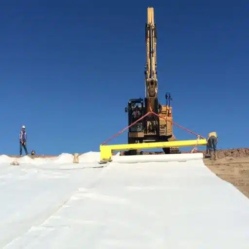
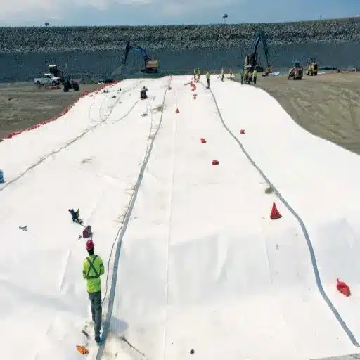
Deployment Techniques
Roll Placement
- Position roll at the upstream or upslope end of the panel
- Unroll in the direction of downslope flow
- Maintain slight tension to prevent wrinkles
- Allow panels to relax before seaming
Handling Requirements
- Use wide-track equipment or place plywood over deployed panels
- Never turn equipment directly on a deployed GCL
- Protect panels from tracked material
- Clean equipment tires before entering the liner area
Panel Orientation
- Orient rolls parallel to slope contours where possible
- Minimize seams on steep slopes
- Stagger panel end joints between rows
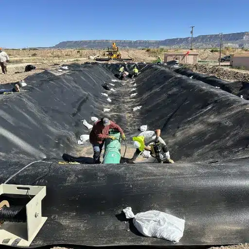
Seaming and Overlap Procedures
Standard Overlap Seams
- Minimum overlap: 150mm for flat areas, 300mm for slopes >10%
- Overlap direction: Downstream or downslope
- Seal method: Apply bentonite paste or granular bentonite at an overlap
- Weighting: Temporary ballast may be required during hydration
Factory-Applied Edge Treatment
- Some GCLs come with factory-applied bentonite at the edges
- Eliminates the need for field application
- Ensure compatibility with the specified sealant method
Panel End Treatment
- Cut ends cleanly with a sharp knife or saw
- Do not pull or tear
- Treat cut edges with bentonite paste to prevent preferential flow
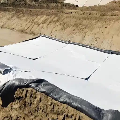
Anchoring Systems for Slopes
Anchor Trenches
- Excavate trenches at the crest of slopes
- Embed GCL minimum 300mm into the trench
- Backfill and compact anchor material
- Detail the geomembrane termination if the composite system
Slope Stability Considerations
- Maximum unreinforced slope: Typically 3H:1V (18°)
- Reinforced GCLs may be used on steeper slopes
- Consider interface friction with the cover soil
- Design for worst-case hydration conditions
Cover Requirements and Protection
Minimum Cover
- Immediate protection: 200mm minimum soil cover
- Permanent applications: 300mm or as specified
- Traffic areas: Minimum 450mm cover
Cover Material
- Select material compatible with GCL
- Avoid angular rock larger than 50mm
- Compact in lifts not exceeding 300mm
- Use low-ground-pressure equipment
Hydration Control
- GCLs can be installed unhydrated or pre-hydrated
- Unhydrated GCLs require prompt covering to prevent premature hydration
- Pre-hydrated GCLs offer advantages in wet climates
Slope Stability and Design Considerations
Sloped applications require careful engineering to ensure long-term stability.
Maximum Recommended Slopes
Standard Needle-Punched GCLs
- 3H:1V (horizontal: vertical) or 18° for most applications
- 2.5H:1V (22°) with proper anchoring and cover
- Steeper slopes require reinforced GCLs
Reinforced GCLs
- Reinforced needle-punched GCLs with enhanced fiber bonding
- May be used on slopes up to 2H:1V (26°)
- Require a detailed slope stability analysis
Reinforced vs Unreinforced GCLs
Unreinforced GCLs
- Standard needle-punched construction
- Adequate for flat to moderately sloped areas
- Lower cost
- Simpler installation
Reinforced GCLs
- Enhanced needle-punching or additional reinforcement
- Higher internal shear strength
- Required for steep slopes or high-stress applications
- Higher cost but necessary for critical applications
Anchor Trench Design
Trench Dimensions
- Depth: Minimum 300mm
- Width: Sufficient for compaction equipment
- Location: At the crest of the slope or designated anchor points
Backfill Requirements
- Use select material free of debris
- Compact to a minimum 95% standard Proctor
- Place in lifts not exceeding 150mm
Interface Friction Considerations
Sliding failures typically occur at interfaces rather than within the GCL itself.
Critical Interfaces
- GCL to subgrade
- GCL to geomembrane (composite systems)
- GCL to cover soil
- GCL internal (reinforced vs unreinforced)
Design Approach
- Test interface friction using direct shear testing (ASTM D5321)
- Use peak or residual strength appropriate for strain conditions
- Apply a safety factor of 1.5 for static conditions
- Consider dynamic loading for seismic areas
Cost Analysis and Economic Benefits
Understanding the total cost picture helps justify GCL selection to project stakeholders.
Material Cost Comparison
GCL vs Compacted Clay (per m²)
- GCL material: $3–8/m² depending on specification
- CCL supply and placement: $8–25/m² including excavation, transport, placement, and compaction
- GCL savings: 40–60% on material and installation combined
GCL vs Geomembrane (per m²)
- GCL material: $3–8/m²
- HDPE geomembrane: $4–12/m²
- GCL offers lower material cost for applications where either would be suitable
Installation Labor Savings
Productivity Comparison
- GCL installation: 2,000–4,000 m² per crew per day
- CCL placement: 200–500 m² per crew per day
- GCL advantage: 5–10x faster installation
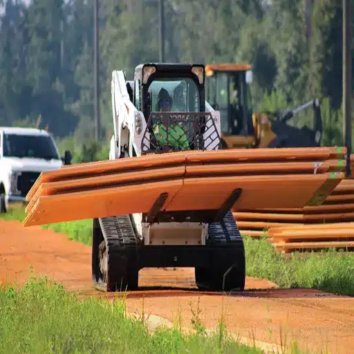
Equipment Requirements
- GCL: Minimal equipment (forklift for rolls, small dozer for cover)
- CCL: Excavators, trucks, dozers, rollers, water trucks
- GCL savings: Reduced equipment rental and mobilization costs
Transportation Efficiency
Truckload Coverage
- One flatbed truck carries approximately 6,000 m² of GCL
- The same truck carries approximately 40 m² equivalent of CCL (imported clay)
- Transportation advantage: 150:1 ratio
For remote projects, this transportation efficiency often determines project feasibility. Importing clay to a remote mine site might cost more than the clay itself, while GCLs arrive in a few truckloads.
Long-Term Performance Value
Quality Control Benefits
- Factory-controlled manufacturing ensures consistent performance
- Reduced risk of failed compaction tests and rework
- Predictable hydraulic conductivity
Service Life Economics
- Design life: 100+ years under normal conditions
- Reduced monitoring and maintenance compared to CCLs
- Self-healing reduces the risk of catastrophic failure
Quality Assurance and Supplier Selection
Selecting the right GCL supplier ensures product quality and project success.
Factory Quality Control Indicators
Manufacturing Standards
- ISO9001 quality management certification
- Documented manufacturing procedures
- In-process quality testing
- Batch records and traceability
Testing Protocols
- Bentonite quality verification (swell index, montmorillonite content)
- Geotextile property confirmation
- Finished product peel strength testing
- Hydraulic conductivity batch testing
Certification Requirements
Minimum Certifications
- ISO9001: Quality management systems
- Product test reports from recognized laboratories
- Material Safety Data Sheets (MSDS)
Additional Certifications (as required)
- ISO14001: Environmental management
- Factory Mutual (FM) approval for specific applications
- Project-specific third-party inspection
Sample Retention Policies
A reliable supplier maintains samples from each production batch for future reference.
Industry Standard Practice
- Retain samples for a minimum of 5 years
- Document storage conditions
- Enable retesting if questions arise
- Provide chain of custody documentation
Technical Support Capabilities
Pre-Sale Support
- Application engineering consultation
- Specification review and recommendations
- Design assistance for unusual conditions
Post-Sale Support
- Installation guidance and supervision
- Quality control testing assistance
- Troubleshooting and problem resolution
Request a quote with technical specifications review included. Contact our engineering team for project-specific recommendations.
Conclusion
Geosynthetic clay liners are a major improvement in containment technology compared to traditional compacted clay because engineers prefer such a liner for its rapid installation and usually lower cost over the lifetime of the project.
Key takeaways:
- GCLs provide equivalent hydraulic performance to 500mm+ of compacted clay in a factory-manufactured product only 8–10mm thick
- Self-healing capability distinguishes GCLs from rigid barriers; bentonite automatically seals around minor damage
- Five GCL types serve different applications: standard needle-punched for general use, coated and composite for chemical resistance, polymer-enhanced for aggressive environments
- Composite systems (GCL + geomembrane) provide redundant protection that exceeds the performance of either material alone
- Proper specification and installation following ASTM standards ensures long-term performance
- Transportation and installation efficiency make GCLs the economical choice for many projects, particularly in remote locations
The increasing relevance of GCLs in demanding applications such as landfill, mining, water management, and environmental must pay for their reliable performances. These are the engineers who know such materials and ensure a very good fit of GCL with very cost-efficient containment solutions that save both dollar costs and environmental goals.
Ready to specify GCLs for your next project?
Request a technical consultation with our engineering team to discuss your specific application requirements, receive product recommendations, and obtain detailed specifications. We provide ISO9001-certified geosynthetic clay liners with comprehensive technical support from specification through installation.