HDPE geomembrane installation is a carefully planned and executed process of putting in and seaming various pieces of high-density polyethylene liner to form a perfect seal for containment purposes. This is where mastering the art of installation becomes very important, as it is essential in preventing leachates from landfills, reservoirs, mining tailings ponds, and wastewater treatment plants, among others. It is also the quickest avenue for containment failure, only less about the material and more about the installation.
Do you have a question about proper HDPE geomembrane material for different applications of thickness or grade? This is only half of the job done because not everything happens in the office. There are also matters like preparation of the subgrade base, thermal installation with changing climate, along with seam checks and consistent quality reports. This article aims to show in detail the entire process of HDPE geomembrane installation, starting from the peripheries and inclinations all the way to the end and handing over the site for use. With particular attention to welding techniques permissible, laboratory examination expressed in ASTM standards, and works carried out at cold temperatures, i.e., in the field.
Key Takeaways
- Subgrade preparation and proper installation mitigate up to 90% of common geomembrane failure modes.
- Hot wedge welding at 300–500°C with dual-track seams creates testable air channels for non-destructive seam verification.
- HDPE thermal expansion requires 1–3% slack allowance (300–500 mm) to prevent stress cracking from temperature fluctuations.
- Cold weather welding demands parameter adjustments: increase temperature by 20–40°C and reduce travel speed by 25–50% below 0°C.
- ASTM D6392 destructive testing requires 25-mm wide samples every 500 linear meters of seam with minimum peel strength of 400 N/50 mm.
What Is HDPE Geomembrane Installation?
HDPE geomembrane installation is the field-engineered process of deploying high-density polyethylene liner panels, joining them with thermal fusion or extrusion welding, anchoring them to resist wind uplift and slope creep, and verifying seam integrity through non-destructive and destructive testing protocols.
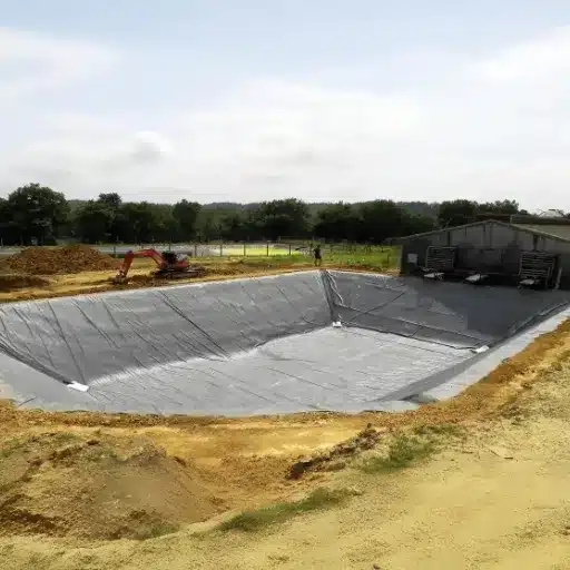
The process applies to any containment system where liquid or gas migration must be controlled. Common applications include landfill base and cap liners, reservoir and pond linings, mining heap leach pads, tailings storage facilities, and wastewater treatment lagoons. HDPE geomembranes offer permeability coefficients as low as 1×10⁻¹³ cm/s, making them among the most impermeable engineered materials available when installed correctly per GRI-GM13 specifications.
However, the material properties, chemical resistance, UV durability, and low permeability only perform when the installation achieves intimate contact with the subgrade, and seam integrity is verified through structured testing. A single compromised weld can negate the performance of an entire containment system.
Want to understand how HDPE compares to other liner materials before you plan installation? Explore our complete HDPE geomembrane guide for material selection, properties, and applications.
Pre-Installation Planning and Site Preparation
Subgrade Requirements
The subgrade is the foundation of every successful installation. A smooth, stable, and well-compacted surface prevents puncture, abrasion, and uneven loading that can stress seams over time.
Prepare the subgrade to these minimum standards:
- Compaction: Achieve ≥93% standard Proctor density across the entire surface. Soft or loose areas will settle under load, creating voids beneath the liner and concentrating stress at seams.
- Surface smoothness: Remove all vegetation, rocks, roots, debris, and sharp protrusions greater than 2 cm. Any hard point pressing against the geomembrane becomes a potential puncture site once cover material is placed.
- Grading and contouring: Grade the surface to achieve the designed slope and drainage pattern. Standing water beneath the liner accelerates subgrade erosion and can balloon the geomembrane off the surface.
The real bombing of Meridian Environmental last autumn was a four-hectare landfill cell located in Northern China, on which a study group sat down to accomplish nothing, working all of three consecutive days on subgrade checking. They would eventually clean up an extra week’s worth of those fourteen concrete blocks traced by Li Wei, their geotechnical engineer. Site investigation confirmed: the substratum would not have withstood these penetrating materials, all exposed to daily wear and tear, be they land or waste, and would have incurred an extra cost of $40,000 during their policy period, multiplied by the ordered land remediation activity for repairs and rediscoveries.
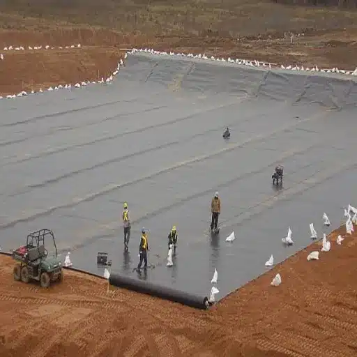
Geotextile Protection
Over various rocky soils, the halls of landfill applications, or mining facilities, use an unwoven geotextile top of the HDPE geomembrane. The cushioning layer is designed to distribute point loading and prevent abrasion between the liner and subgrade.
Besides adequate puncture resistance to be provided with the type of cover material and traffic loads anticipated, at ERCs, one should have a geotextile about 30 cm beyond the geomembrane edges at all terminations to provide continuous protection. The geotextile also stops bentonite migration into the seam area of the composite liner systems, combining a geosynthetic clay liner and HDPE.
Penetrations and Obstacles
There is extremely intricate work for openings related to major pipelines, structural columns, and bedrock outcrops. Different requirements are, therefore, spelled out for these components. HDPE pipe boots are fashioned from the same material used in the finding of the membrane specification, then a thickness of not less than 1.5mm. The whole of the aforementioned boots is welded by extrusion welding around the entire surface and then finished with a capping fillet.
For that boulder or maybe unforeseen hard obstruction, you will need to top off the area with the use of closed-cell foam boards with a granular fill layer that has a minimum thickness of 50 mm, with an exhausted 100 kPa compressive strength, and compacted at the ducted depth to subgrade density. Do not install under stress caused by the HDPE geomembrane uncovering rough rock faces.
Environmental Condition Assessment
Weather conditions control weld quality and material handling. Schedule work within these parameters:
| Parameter | Acceptable Range | Action if Exceeded |
|---|---|---|
| Ambient temperature | 5°C to 40°C | Suspend welding; implement cold-weather protocol below 5°C |
| Wind speed | <20 km/h (Beaufort Level 4) | Secure panels with additional ballast; suspend unrolling above 20 km/h |
| Precipitation | <5 mm/hour | Stop work if rain exceeds the threshold; dry all surfaces before resuming |
| Subgrade moisture | <20% | Dry soil or add lime treatment before liner placement |
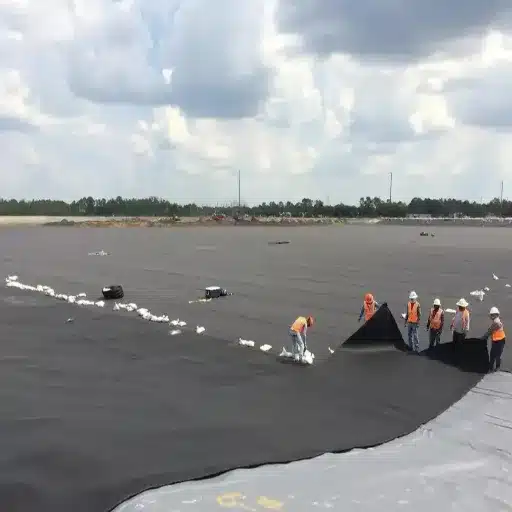
Panel Deployment and Layout Strategy
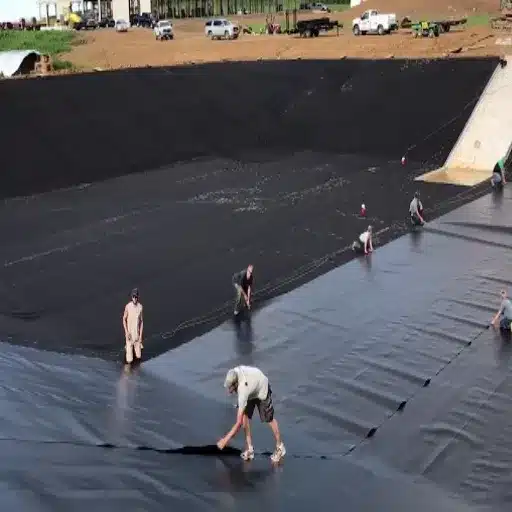
Roll Handling and Unrolling
HDPE geomembrane rolls typically weigh 500–1,000 kg and require mechanical handling. Use winches, spreader bars mounted on excavators, or forklifts with padded forks. Never drag sheets across the prepared subgrade; friction abrades the surface and introduces contaminants that weaken welds.
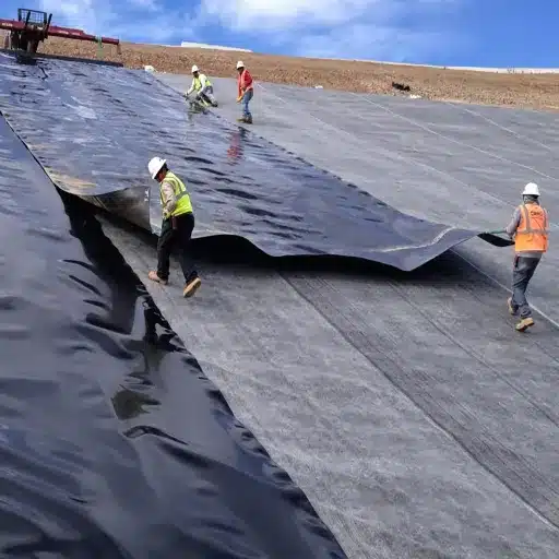
Orient panel seams parallel to the slope direction (up and down the slope), not perpendicular. Cross-slope seams create direct pathways for liquid migration if weld failure occurs, and they experience higher shear stress from settlement and loading. Seams running parallel to the slope align with the primary stress direction and are easier to anchor against downslope creep.
Positioning and Overlap
On a slope of less than 3:1, hot-wedge-weld adjacent panels. However, increase the overlap by 200 mm on steeper slopes to gain substrate resistance in the weld seam. Once proper dimensional conditions have been analyzed, future panel welding should be done at 2 m intervals along the full length of the seam to control the welding.
HDPE depends on the temperature because if the temperature changes, it moves away from the panel. Even when installed at some cooler temperatures during the morning, lining will shrink still further in winter, exerting a thrust on anchor trenches and stressing the seam. Allow for a space of 1–3% (meaning typically 300–500 mm for each panel) to allow for thermal movement before installation, with respect to installation conditions as well as service temperatures.
Temporary Anchoring
Secure panel edges with sandbags (20–30 kg each) spaced 1–2 meters apart. Do not stake through the geomembrane; any penetration creates a permanent breach in the impermeable barrier. On windy sites, increase ballast density or use continuous soil berms along the panel perimeter.
Wrinkle Management
Wrinkles and fishmouths are among the most common installation defects. They fold over under cover material loading, creating high-stress crack zones where the liner fails prematurely. Manage wrinkles through three field practices:
- Schedule deployment during the coolest part of the day (early morning or late evening) when the liner is contracted and easier to lay flat.
- Deploy only what can be welded, anchored, and covered within the same shift. Exposed liner heats in sunlight, expands, and forms wrinkles that become difficult to remove.
- Use the “push, accumulate, cut, and seam” method. When wrinkles form along an overlap, push excess material toward the seam edge, cut the excess at the coolest time of day, and extrusion-weld the cut edge before hot-welding the main seam.
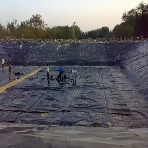
Seaming and Welding Procedures
Seams represent the most vulnerable part of any HDPE geomembrane installation. Approximately 80% of containment failures attributable to installation originate at seams. Proper surface preparation, equipment calibration, and parameter control are non-negotiable.
Surface Preparation
Clean all overlap areas before welding. Use a lint-free cloth soaked in isopropyl alcohol (99% purity) to remove dust, moisture, oxidation, and organic contaminants. Any residue between the overlapping sheets prevents molecular fusion and creates a weak bond.
When ambient temperature drops below 10°C, preheat the panel overlap zone to approximately 15°C using infrared heaters or heated air guns. Cold HDPE surfaces resist fusion even when the wedge or extrusion gun reaches target temperature.
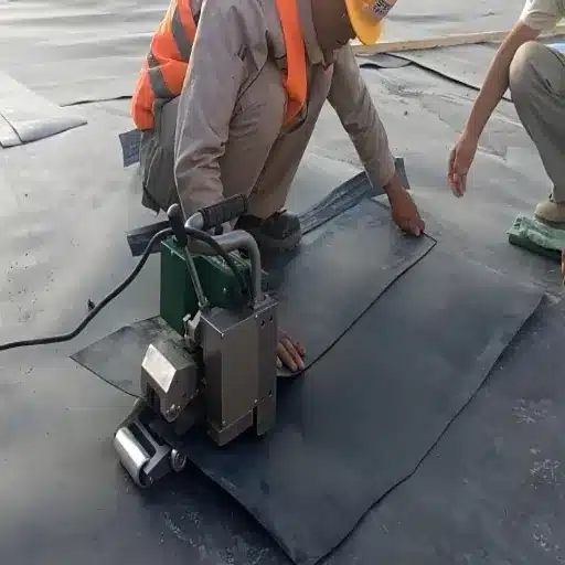
Hot Wedge Fusion Welding
Hot wedge welding joins long, straight field seams by melting overlapping sheet edges with a heated blade and bonding them under pressure. It produces the strongest, most consistent seams when parameters are controlled.
| Ambient Condition | Wedge Temperature | Travel Speed | Roller Pressure |
|---|---|---|---|
| Warm (20–40°C) | 300–380°C | 2.0–3.0 m/min | 0.3–0.4 MPa |
| Moderate (10–20°C) | 350–420°C | 1.5–2.5 m/min | 0.3–0.5 MPa |
| Cool (5–10°C) | 380–450°C | 1.2–2.0 m/min | 0.4–0.5 MPa |
| Cold (0–5°C)* | 400–500°C | 1.0–1.5 m/min | 0.4–0.5 MPa |
See the cold-weather protocol section for sub-zero adjustments.
Use dual-track welding equipment to create two parallel weld beads with an internal air channel between them. This channel enables air pressure testing, the most reliable non-destructive seam verification method for field welds.
Beginning each work shift, perform trial welds on scrap material using the exact parameters planned for that day’s conditions. Cut 25-mm wide samples from trial welds and perform peel tests. The parent material must tear before the seam separates. If the seam peels cleanly, increase the temperature or reduce travel speed and retest.
Need HDPE geomembrane materials manufactured to consistent specifications for your next project? Browse our engineered HDPE geomembrane liners with thickness options from 0.5 mm to 3.0 mm for tailored containment performance.
Extrusion Welding
Extrusion welding repairs damaged areas, joins T-junctions, seals pipe penetrations, and completes detail work where wedge welders cannot reach. A welding gun extrudes molten HDPE rod (matching the liner resin) at 200–250°C into a V-shaped groove prepared between the sheets.
| Parameter | Specification |
|---|---|
| Extrusion temperature | 200–250°C |
| Rod extrusion rate | 3–5 kg/hour |
| Fillet weld depth | 5–10 mm minimum |
| Pre-ground groove angle | 45° |
Grind the weld area to remove oxidation and create a clean bonding surface. The grinding depth must not exceed 10% of the sheet thickness to avoid compromising liner integrity.
Weld Quality Verification
Every weld must display a cohesive fracture during destructive peel testing. A cohesive fracture is defined as when the parent material of HDPE fails before the seam tears off, thereby showing you that the weld was always stronger than the sheet. If the failure was adhesive (the seam tore cleanly), the weld parameters were insufficient, or there was contamination on the surface.
Track each weld test according to temperature, speed, pressure, operator’s identification, and pass/fail result. These sets of data will form the construction quality control (CQC) file.
Cold Weather Installation Protocol
Standard HDPE geomembrane installation assumes ambient temperatures above 5°C. When projects in northern climates, high-altitude sites, or winter construction windows require sub-zero installation, material selection and welding parameters must change.
Material Specifications for Cold Environments
Specify cold-weather-grade HDPE with:
- Brittleness temperature ≤ -35°C per ASTM D746
- Thickness ≥1.5 mm for structural robustness during handling
- Density between 0.940–0.965 g/cm³ per ASTM D1505
- Freeze-thaw retention: minimum 80% elongation after 50 freeze-thaw cycles
Standard thinner sheets become brittle below -10°C and crack during unrolling or welding manipulation.
Welding Parameter Adjustments
| Temperature Range | Wedge Temperature | Travel Speed | Roller Pressure |
|---|---|---|---|
| 0°C to -5°C | 180–200°C | 1.5–2.0 m/min | 0.3–0.4 MPa |
| -5°C to -10°C | 200–220°C | 1.0–1.5 m/min | 0.4–0.5 MPa |
| Below -10°C | 220–240°C | 0.8–1.2 m/min | 0.4–0.5 MPa |
Below -10°C, consider suspending welding operations entirely unless the project timeline demands continuation. Even with adjusted parameters, weld quality becomes inconsistent, and the risk of cold-induced brittle failure in the parent sheet increases.
Site Preparation in Freezing Conditions
Remove all soil frosts, ice, and snow from the subgrade on the laying of a liner. When soil moisture exceeds 20%, either dry the subgrade or treat it with lime to prevent frost heaving once the liner is in place. This creates unfilled space areas under the geomembrane where the thawing soil occurs over the laid liner.
When a Russian mining contractor installed a tailings pond liner at -18°C in January 2024, their crew worked in four-hour shifts to prevent equipment freezing and operator fatigue. They preheated all panel overlap zones with propane infrared heaters, stored HDPE welding rod in insulated containers, and reduced daily production targets by 60%. The result: zero seam failures in post-installation testing, compared to a 12% rework rate on a comparable project three years earlier that had attempted normal parameters in sub-zero conditions.
Quality Assurance and Testing
Quality assurance is divided into non-destructive testing (NDT) for 100% seam coverage and destructive testing for statistical verification. Both are required under HDPE geomembrane testing standards, ASTM D6392, and IAGI installation guidelines.
Non-Destructive Testing (NDT)
| Test Method | Application | Procedure | Acceptance Criteria |
|---|---|---|---|
| Air pressure testing | Dual-track hot wedge seams | Seal channel ends; inject compressed air | <10% pressure decay per minute at 20–200 kPa |
| Vacuum box testing | Extrusion welds, patches, details | Apply surfactant; draw 0.3–0.5 kPa vacuum | No bubble formation during 10-second hold |
| Spark testing | Conductive-backed geomembranes | Scan at ~20 kV across seam area | No arc discharge; detects holidays <0.5 mm |
| Electrical leak location (ELL) | Covered or submerged liners | Gradient array or water lance method | Map anomalies for excavation and repair |
Air pressure testing is the primary NDT method for field seams. Pressurize the internal channel created by dual-track welding and monitor pressure decay. A decay rate exceeding 10% per minute indicates a leak in the seam; locate the breach with soapy water or ultrasonic detection, then repair with extrusion welding and retest.
Destructive Testing
Cut 25-mm wide samples every 500 linear meters of seam (minimum one sample per seam, per shift, per welding machine). Test for peel strength and shear strength per ASTM D6392. The minimum acceptable threshold is typically 400 N/50 mm or 90% of the parent sheet strength, whichever is lower.
If any sample fails, extend destructive testing to 100-meter intervals along the suspect seam section. Rework all seams in the failed zone and retest until two consecutive samples pass.
Construction Quality Assurance (CQA) Documentation
Systematic documentation protects the project owner, the installer, and the material supplier. Maintain these records throughout installation:
- Welding logs: Temperature, speed, pressure, ambient conditions, operator ID, equipment number, and pass/fail result for every seam
- Material traceability: Roll numbers, batch numbers, manufacturing dates, and mill certificates for all HDPE delivered to the site
- Testing records: NDT results with seam identification, pressure readings, and inspector signatures; destructive test results with laboratory reports
- Photographic record: Pre-installation subgrade, panel layout, seam close-ups, testing operations, and as-built configuration
- Third-party inspection reports: Independent CQA inspector observations and sign-offs at defined hold points
For large-scale projects, including landfills, tailings dams, and municipal reservoirs, engage a third-party CQA firm to verify installer CQC practices. The cost of independent inspection is negligible compared to the cost of post-commissioning liner failure and environmental remediation.
Anchoring, Edge Protection, and Backfilling
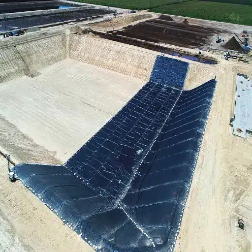
Anchor Trench Design
Perimeter anchor trenches prevent wind uplift and hold the liner in position during backfilling and service. Standard trench dimensions range from 0.5 m × 0.5 m to 0.75 m wide × 0.6–1.0 m deep, depending on wind exposure, slope gradient, and cover material weight.
Drape the geomembrane 300–500 mm into the trench, then backfill with compacted soil containing particles no larger than 50 mm. Compact backfill to 90–95% standard Proctor density in 150–200 mm lifts. Avoid heavy compaction equipment within 1 meter of the liner edge to prevent crushing or tearing.
On steep slopes exceeding 3:1, install intermediate key trenches every 10 meters horizontally. These trenches interlock the liner with the slope and resist downslope creep from thermal cycling and cover settlement.
Edge Protection Systems
For pond and reservoir applications where the liner terminates at a free edge, protect the geomembrane with concrete or stone caps, a minimum of 100 mm thick. The cap prevents UV degradation of the exposed edge and resists wave action erosion.
In high-wind environments, supplement anchor trenches with J-hooks or rebar pins driven into compacted backfill at 1-meter spacing along the perimeter. Do not pin through the geomembrane; anchor only the backfill mass that holds the liner.
Backfilling Protocol
Place cover material promptly after seam acceptance testing. Delayed covering exposes the liner to UV damage, wind uplift, and accidental puncture from site traffic. Use fine-grained soils without sharp fragments, placed in 200-mm lifts. Monitor for wrinkle displacement during backfill placement and flatten any wrinkles exceeding 50 mm in height before adding the next lift.
Planning a pond or reservoir lining project? Review our guide to HDPE geomembrane pond liner systems for application-specific thickness and anchoring recommendations.
Troubleshooting and Repair Procedures
Even with rigorous planning, field conditions produce defects. A structured repair protocol prevents minor issues from becoming project failures.
Common Field Issues
- Wrinkles and fishmouths: From when weld preparation deflates the liner in heat before welding or if there is subsoil settlement at strata.
- Contaminated weld areas: Dust, moisture, or organic matter infiltrated during surface preparation or dust blown by the wind.
- Punctures from equipment or debris: Come about when heavy equipment runs too close to the liner on the surface or even when hidden objects dent the sheet.
- Thermal stress cracking: To cause happen because too much tension remains in the liner, so that it contracts in cold weather as it is installed.
Repair Decision Tree
| Defect Type | Repair Method | Minimum Patch Size | Retest Requirement |
|---|---|---|---|
| Minor puncture (<25 mm) | Extrusion-welded patch | 150 mm × 150 mm with 50 mm overlap | Vacuum box test |
| Seam defect (localized) | Cut and re-weld, or extrusion cap over the defect | Extend 100 mm beyond the visible flaw | Air pressure + destructive test |
| Large tear or panel damage | Panel replacement with a new sheet | Minimum 300 mm overlap on all sides | Full NDT + destructive test |
Grind the repair area to remove oxidation and create a V-groove for extrusion welding. The grinding depth must not exceed 10% of the sheet thickness. After welding, allow the repair to cool to ambient temperature before testing. Document every repair with GPS coordinates, photographs, repair method, materials used, and test results.
Post-Installation Protection and Commissioning
Traffic Restrictions
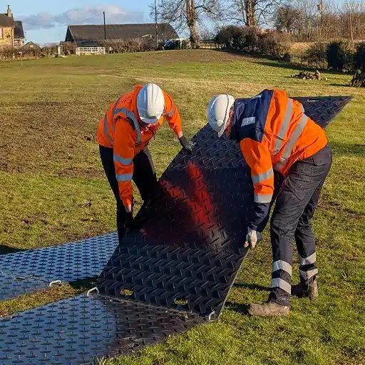
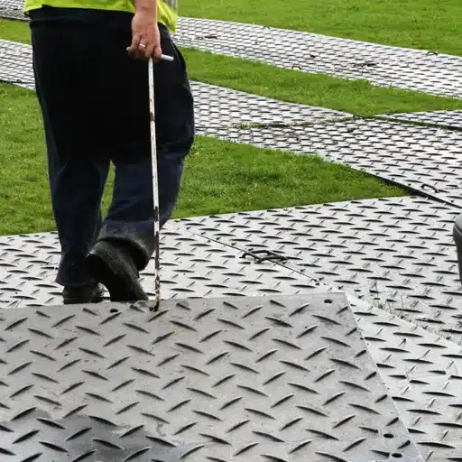
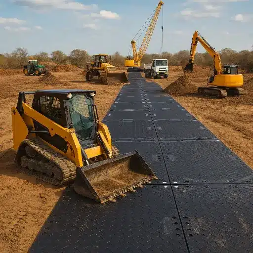
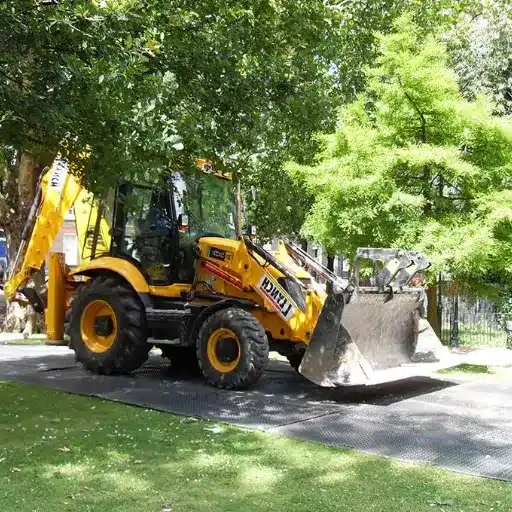
Never drive heavy equipment directly on the installed HDPE geomembrane. If unavoidable access is required, for example, to place cover material on large reservoirs, use temporary ground protection mats or multiple layers of heavy-duty geotextile to distribute loads. Track vehicles exert point pressures exceeding 500 kPa, which exceeds the puncture resistance of most standard HDPE geomembranes.
Cover System Placement
Cover the geomembrane with the specified protective layer as soon as possible after installation and testing acceptance. For exposed geomembranes in reservoir or pond applications where no soil cover is used, specify UV-stabilized HDPE with carbon black content ≥2% per ASTM D1603. Even UV-stabilized liners degrade over time when exposed to direct sunlight; design cover placement within 30 days of installation where feasible.
Commissioning Checklist
Before handover to the project owner, complete these verification steps:
- Final visual inspection of 100% of the installed liner surface
- Verification that all seams have passed NDT (air pressure or vacuum box)
- Destructive test results reviewed and accepted by the CQA inspector
- All repair locations identified, documented, and retested
- As-built drawings submitted showing panel layout, seam locations, and anchor trench positions
- Welding logs, material certificates, and test records compiled in the CQC/CQA file
- Warranty documentation issued, including material sample retention terms
At Shanxi Shengxing, we retain material samples for five years to support traceability and warranty claims. This practice aligns with ISO9001 quality management standards and provides long-term accountability for engineered HDPE geomembrane solutions delivered to global infrastructure projects.
Conclusion
Installing a high-density polyethylene geomembrane is crucial because five primary factors need to be interconnected: preparation of the subgrade to eliminate puncture risks, deployment of panels to take into account thermal expansion, welding methods adjusted to prevailing ambient conditions, tight seam testing that can discover defects before covering, and systematic documentation protecting parties through the project lifecycle.
And one factor increases the others. For example, the perfect weld seam that ties every object tightly positioned in an inadequately prepared subgrade will eventually fail, caused by a hidden rock puncturing the liner. Properly prepared sites will generate leakage through poorly tested seams at those seams. This is in treating every phase with the same rigor.
For project managers and procurement buyers, the selection of material suppliers is essential to avoid excess square meter pricing. The supplier whose resin specifications will always be consistent among different orders offers very attractive improvements: batch testing is traced, and the technical assistance they provide would definitely mitigate all the risks that any installation would have before the roll-to-site reaches the field.
Ready to source HDPE geomembrane materials for your containment project? Request a technical quote with your project specifications, and our engineering team will recommend the right thickness, grade, and delivery schedule for your installation timeline.
FAQ: HDPE Geomembrane Installation
What is the ideal temperature for HDPE geomembrane installation?
A good working temperature would be within 5°C to 40°C. Below 5°C, the HDPE is still flexible enough to be able to fray and crack freely, and the welding equipment gives proper and constant attention for a consistent fusion welding without overextending any parameters.
How much overlap is needed for geomembrane seams?
Standard hot wedge welding requires 100–150 mm overlap between adjacent panels. On slopes steeper than 3:1, increase overlap to 200 mm for additional shear resistance. Extrusion welding detail work requires a minimum 75 mm overlap with a properly prepared V-groove.
What testing is required after welding HDPE geomembrane seams?
All seams require non-destructive testing: air pressure testing for dual-track wedge welds, vacuum box testing for extrusion welds, and details. Additionally, cut 25-mm wide destructive samples every 500 linear meters per ASTM D6392 to verify peel and shear strength.
Can HDPE geomembrane be installed in cold weather?
Yes, with cold-weather-grade material (brittleness temperature ≤ -35°C) and adjusted welding parameters. Increase wedge temperature by 20–40°C, reduce travel speed by 25–50%, and preheat panel overlaps to 15°C before welding. Below -10°C, consider suspending operations.
Why do wrinkles form in HDPE geomembrane during installation?
Wrinkles form primarily from thermal expansion when liner panels heat in sunlight after placement. HDPE expands significantly with temperature; allow 1–3% slack during deployment and install during cooler parts of the day to minimize wrinkle formation.