Proper geotextile installation requires five sequential stages: subgrade preparation, unrolling and positioning, overlap or seaming, anchoring, and controlled aggregate placement. Skip any stage, and the fabric will not perform as engineered.
A contractor in Queensland learned this on a 12-hectare landfill capping project. The crew rolled out a 600 gsm nonwoven geotextile over a poorly prepared subgrade, left it exposed for 34 days during a scheduling dispute, and backfilled with aggregate dropped from 1.5 meters. When the first compaction pass began, the fabric tore in six locations. The remediation required full excavation, replacement, and re-compaction. The direct cost exceeded $48,000. The root cause was not the fabric. It was the installation protocol.
Industry data confirms this pattern. Approximately 80% of geotextile failures result from improper material selection or installation errors, not material defects. The fabric on the Queensland site met every ASTM specification. The crew simply failed to follow the basic rules that govern field performance.
This guide provides those rules. You will learn a complete step-by-step installation protocol, overlap requirements based on subgrade strength, anchoring methods for different site conditions, UV exposure limits, and the seven most common mistakes that destroy geotextile performance before the first load arrives.
Key Takeaways
- Approximately 80% of geotextile failures stem from installation errors, not material defects.
- Overlap requirements range from 300 mm on firm ground to sewn seams on very soft subgrades (CBR < 0.5).
- UV exposure limits vary from 14 days for lightweight fabrics to 30 days for carbon-black-stabilized heavy fabrics.
- Aggregate must be placed using a minimum 150 mm first lift; dropping stone from height causes puncture failures.
- A post-installation inspection checklist prevents 90% of cover-stage failures.
Pre-Installation: Site Preparation and Material Inspection
Installation quality begins before the first roll leaves the truck. Subgrade condition and material handling determine whether the fabric survives the first 24 hours.
Subgrade Preparation
The subgrade must be cleared of all vegetation, roots, loose rocks, and debris larger than 25 mm. Sharp objects puncture fabric during placement or under the first compactive effort. Uncompacted soil creates voids beneath the geotextile, allowing wrinkles that trap water and reduce the contact area.
Grade the surface to eliminate high and low spots. The geotextile must lie in intimate contact with the soil across the entire placement area. Where the subgrade is soft or variable, scarify the top 50 mm and re-compact to uniform density before rolling out fabric.
For road construction and soil stabilization applications, subgrade preparation is especially critical. See our geotextile soil stabilization technical guide for CBR-based preparation standards.
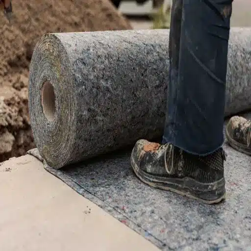
Material Handling and Storage
Geotextile rolls should be stored off the ground on pallets, protected from standing water and direct UV exposure. Polypropylene and polyester polymers absorb moisture and degrade under prolonged sunlight. If rolls must sit on site for more than 48 hours, cover them with opaque sheeting.
Inspect each roll before deployment. Check the label for ASTM compliance, roll weight, and width. Verify that the fabric grade matches the specification. A common field error is deploying the wrong GSM or AOS because the rolls were not labeled clearly at delivery.
How to Install Geotextile Fabric: Step-by-Step Protocol
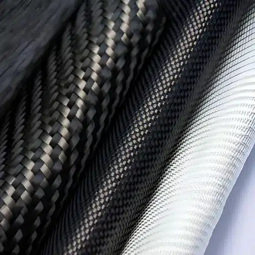
This protocol applies to woven and nonwoven geotextile installation across roads, drainage systems, erosion control, and retaining wall applications. Adjust details based on site-specific engineering requirements.
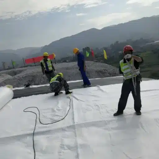
Step 1 — Unrolling and Positioning
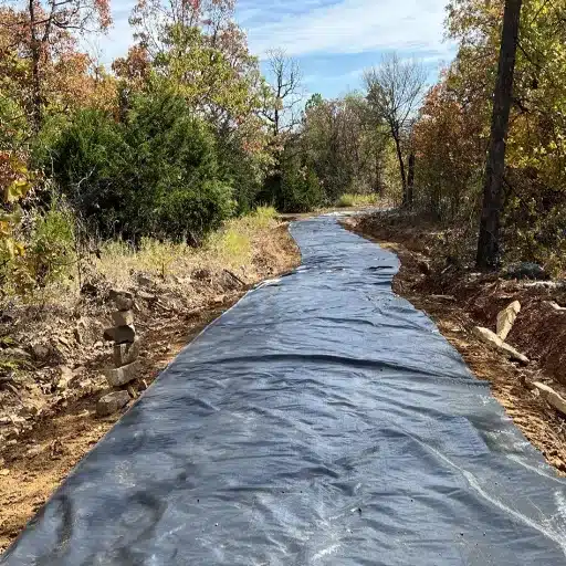
Place rolls with the machine direction parallel to the primary stress orientation. For road construction, this means parallel to traffic. For drainage channels, align with the flow direction. Woven geotextiles exhibit anisotropic strength, with grab tensile typically 10-15% higher in the machine direction than the cross-machine direction. Incorrect orientation reduces effective load-bearing capacity.
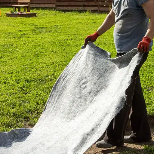
Unroll smoothly without stretching or dragging. The fabric should lie flat with minimal slack. Excessive slack creates wrinkles that pool water and reduce effective coverage. Over-tensioning risks tearing at overlap points or anchor locations.
For woven geotextile applications requiring high tensile performance, directional placement is non-negotiable. Review our woven geotextile applications and selection guide for project-specific orientation guidance.
Step 2 — Overlap Rules by Subgrade Condition
Overlap is the most frequently botched step in geotextile installation. The correct overlap distance depends on subgrade strength, measured by California Bearing Ratio (CBR), and on hydraulic or slope conditions.
| Subgrade CBR | Field Condition | Minimum Overlap | Seam Method |
|---|---|---|---|
| < 0.5 | Very soft; cannot support walking | Sewn seam required | Sewn (ASTM D4884) |
| 0.5 – 1 | A person can walk without significant rutting | 900 mm (3 ft) | Overlap or sewn |
| 1 – 2 | Low-ground-pressure equipment without deep ruts | 600-750 mm (2-2.5 ft) | Overlap |
| > 2 | Firm ground; standard equipment access | 300-450 mm (1-1.5 ft) | Overlap |
Slope and hydraulic adjustments:
- Slopes steeper than 10%: increase overlap to 600 mm minimum
- Underwater or below-water installations: 1,000 mm minimum
- Very soft or critical hydraulic structures: sewn seams at 1,000 mm overlap
Shingling direction matters. On slopes, the upslope sheet must overlap the downslope sheet. In channels, the upstream sheet overlaps the downstream sheet. This prevents water or fines from infiltrating the joint. Overlaps should face the direction of aggregate placement to prevent lifting during backfilling.
AASHTO M288 provides the foundation for these overlap rules. For a deeper reference on test methods and survivability classes, see our ASTM standards explained guide.
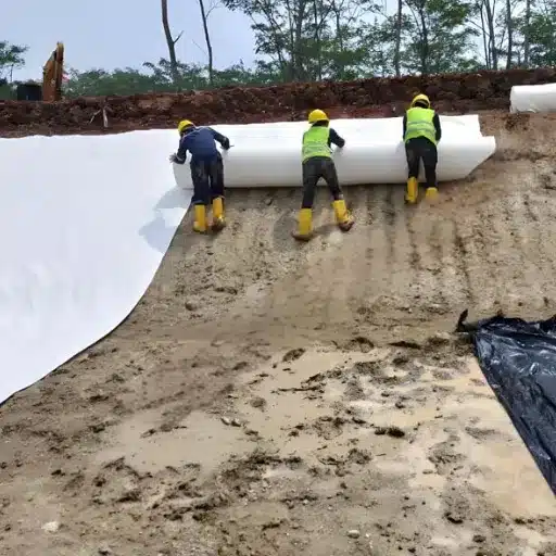
Step 3 — Anchoring and Securing
Unsecured geotextile shifts during backfilling, wind events, or equipment movement. Three anchoring methods cover most site conditions.
Staples and pins: Use 150-450 mm long, 11-gauge U-staples or geotextile pins. On flat ground, space staples at 1-3 meter intervals along edges and overlaps. On slopes or high-traffic areas, reduce spacing to 0.5 meters. Stagger fasteners rather than placing them in straight lines for better resistance to pull-out.
Anchor trenches: Required at the crest and toe of slopes and at the upstream terminus of channels. Minimum dimensions are 150 mm deep by 150 mm wide. For steep or critical slopes, excavate 300 mm deep trenches, place the fabric edge, and backfill with compacted soil at a minimum 90% Proctor density.
Temporary ballast: Sandbags (10-50 kg), soil mounds, or rock weights hold edges and leading edges during placement. This method is preferred over excessive pinning on sensitive subgrades where staple penetration could damage the fabric or underlying geomembrane.
For erosion control applications on steep slopes, anchoring demands increase significantly. Our geotextile erosion control applications guide covers slope-specific anchoring protocols.
Step 4 — Seaming vs. Overlapping
Most installations use simple overlap. Seaming is required only under specific conditions.
| Method | When to Use | Requirement |
|---|---|---|
| Overlap | Standard separation and stabilization on firm to moderately soft soils | Follow the CBR table above |
| Sewn seam | CBR < 0.5; critical reinforcement; steep slopes; large hydraulic structures | Seam strength >= 80% of geotextile tensile strength per ASTM D4884. Use UV-resistant polypropylene or polyester thread. Federal Stitch Type 401 (dual-thread lock stitch) is standard for woven geotextiles. |
| Heat-sealing | Nonwoven geotextiles where sewing is impractical | Can achieve 95-98% seam integrity when performed correctly |
Seams are the weakest structural point in any geotextile installation. Even a properly sewn seam achieves only 80% of the parent fabric strength. Design engineers must account for this reduction in safety factor calculations.
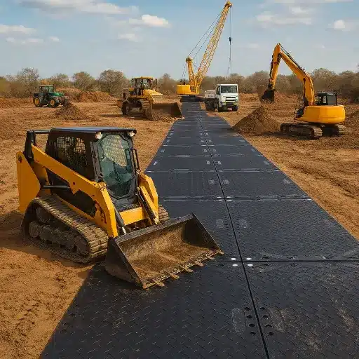
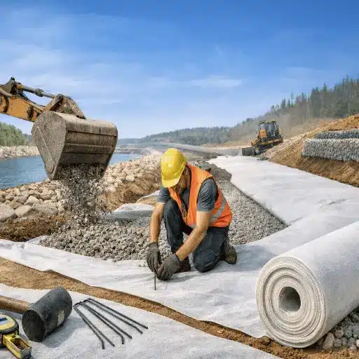
Step 5 — Aggregate Placement and Cover
The first aggregate lift is the most dangerous phase for geotextile integrity. A sharp stone dropped from a height punctures the fabric. Equipment trafficking directly on the geotextile causes tears and displacement.
Minimum first lift thickness: 150 mm. Use thicker lifts over soft subgrades to limit rutting to less than 100 mm.
Equipment protocol: Use tracked bulldozers with low ground pressure on soft subgrades. Blade into the leading edge and push slightly upward to prevent dragging the fabric. Avoid sudden stops, sharp turns, and direct trafficking on the geotextile whenever possible.
Drop height: Do not drop aggregate from more than 300 mm above the fabric surface. A 1-meter drop of sharp aggregate generates approximately 85 lbs of impact force, sufficient to puncture most geotextiles, especially if UV-degraded.
On very soft subgrades, watch for mud waves caused by overstressing the subgrade during compaction. If severe rutting occurs, consult the project engineer for staged filling procedures rather than continuing with standard lift thicknesses.
For drainage system installation where aggregate surrounds the fabric in a trench configuration, see our nonwoven geotextile drainage guide for the burrito-wrap method and trench-specific protocols.
Geotextile Overlap Requirements: The CBR-Based Decision Framework
Overlap is not a one-size-fits-all specification. The APWA 2025 Standard Specifications state that unless otherwise noted on plans, geotextile shall be overlapped at least 600 mm at all joints, or the geotextile shall be sewn. But 600 mm is a default, not an optimum.
On firm subgrades with CBR above 2, a 300 mm overlap is sufficient for separation and filtration applications. The subgrade provides enough support that joint displacement is minimal. On very soft subgrades with CBR below 0.5, even a 900 mm overlap will pull apart under equipment loading. Only a sewn seam provides adequate integrity.
Slope considerations: On slopes steeper than 10%, increase all overlap distances by 50%. Gravity and construction traffic create downward shear forces that standard overlaps cannot resist. Anchor trenches at the crest become mandatory, not optional.
Underwater installations: Below-water placement requires 1,000 mm minimum overlap because turbidity prevents visual confirmation of joint alignment, and currents can displace fabric before cover material is placed.
Anchoring Methods for Different Site Conditions
The anchoring method must match the site geometry, subgrade strength, and exposure duration.
Flat ground, temporary exposure: Staples at 1-3 m intervals along all edges and overlaps. Supplement with sandbags at roll ends if wind is forecast.
Slopes up to 10%: Staples at 0.5 m intervals. Anchor trenches at crest and toe. Temporary ballast on the leading edge during unrolling.
Slopes exceeding 10%: Staples at 0.5 m intervals in a staggered pattern. Anchor trenches minimum 300 mm deep at crest and toe. Consider sewn seams for all overlaps. Reduce equipment trafficking to essential passes only.
Retaining wall applications: Geotextile behind retaining walls requires specific anchoring at the wall face and staged backfilling to prevent fabric displacement during compaction. Our geotextile retaining wall installation guide covers wall-specific protocols, including drainage composite integration.
Channel and hydraulic applications: Anchor trenches at the upstream end. Overlap upstream over downstream. Place ballast on the leading edge before beginning backfilling to prevent current displacement.
UV Exposure Limits and Protection Protocols
UV radiation is the silent killer of exposed geotextile. Polymer chain scission occurs primarily in the 290-400 nm range, degrading tensile strength before the fabric is ever loaded.
| Fabric Weight | Maximum UV Exposure | Notes |
|---|---|---|
| Lightweight (100-150 gsm / 3-4 oz/yd²) | 14 days | Bury immediately |
| Medium weight (200-270 gsm / 6-8 oz/yd²) | 21 days | Standard construction schedule |
| Heavyweight (400-600 gsm / 10-12 oz/yd², carbon black stabilized) | 30 days | Extended exposure rated |
| General rule | 24-72 hours | Ideal cover timing |
Polymer differences: Polyester (PET) is approximately 30% more UV-resistant than polypropylene (PP). However, PET hydrolyzes in high-pH soils above pH 10, a failure mode that UV stabilizers cannot prevent. PP loses 30-50% of tensile strength after approximately 500 hours of UV exposure under ASTM D4355 test conditions.
Environmental amplifiers:
- Altitude: UV intensity increases approximately 26% at 1,600 m (5,280 ft) versus sea level. Safe exposure time drops to roughly 11 days in peak summer at altitude.
- Snow: Reflects approximately 80% of UV radiation, effectively doubling the dose on vertical installations such as retaining walls and slope faces.
- Heat: Exposed fabric in trenches can reach 60°C, doubling chemical degradation speed.
Inspection signs of UV damage:
- Chalky white powder on fiber surfaces
- Brittleness: fabric snaps at 12-15% elongation versus original 50%+
- Tearing under minimal thumb pressure
If UV damage is suspected, remove and replace the affected section. Do not attempt to cover damaged fabric and hope for recovery. Degradation is irreversible.
The 7 Most Common Geotextile Installation Mistakes
These seven mistakes account for the majority of field failures. Each is preventable with proper planning and crew training.
Mistake 1: Inadequate subgrade preparation
Leaving rocks, roots, or debris larger than 25 mm beneath the geotextile creates puncture points. Uneven surfaces create voids that allow fabric wrinkles and reduce the effective contact area. The solution is simple: clear, grade, and compact before unrolling.
Mistake 2: Wrong overlap for soil conditions
Applying a 300 mm overlap on soft subgrade with CBR below 1 guarantees joint failure under the first equipment pass. Match overlap distance to CBR using the decision table above. When in doubt, increase overlap or specify sewn seams.
Mistake 3: Exceeding UV exposure limits
A 21-day exposure limit means 21 calendar days, not 21 working days. Weather delays, scheduling conflicts, and procurement issues routinely push exposure past safe limits. Track exposure time from the moment the fabric is unrolled. If the cover is delayed beyond the rated limit, specify UV-stabilized material or plan for replacement.
Mistake 4: Dropping aggregate from height
Dumping sharp stone from truck beds or excavator buckets directly onto geotextile causes impact punctures. A 1-meter drop generates approximately 85 lbs of force on a small contact area. Use padded buckets, lower drop heights to 300 mm maximum, or place a 100 mm sacrificial sand layer before coarse aggregate.
Mistake 5: Equipment trafficking on exposed fabric
Driving loaders, trucks, or compaction equipment directly on the geotextile causes tears, ruts, and displacement. Woven geotextiles experience approximately 26% strength loss in the cross-machine direction when trafficked before cover placement. The rule is clear: no equipment on bare fabric.
Mistake 6: Insufficient edge anchoring on slopes
Fabric edges left unsecured on slopes slide during backfilling or under heavy rain. Anchor trenches at the crest and toe are not optional on slopes exceeding 10%. Without them, the fabric migrates downhill, exposing the subgrade and creating erosion gullies.
Mistake 7: Using the wrong fabric type for the function
Installing a nonwoven geotextile for heavy-load reinforcement, or a woven slit-film geotextile for fine-grained soil filtration, invites failure regardless of how perfectly the installation protocol is followed. Fabric selection precedes installation. For guidance on matching fabric type to project function, see our woven vs nonwoven geotextile comparison.
Post-Installation Inspection Checklist
Before authorizing cover placement, verify each item on this checklist. A 10-minute inspection prevents a 10-day remediation.
- Subgrade is clear of debris, roots, and sharp objects larger than 25 mm
- Fabric grade matches specification (ASTM, AOS, GSM, width)
- Roll orientation is correct (machine direction aligned with primary stress)
- Overlap distance meets or exceeds the CBR-based requirement
- Shingling direction is correct (upslope over downslope, upstream over downstream)
- Staples or pins are spaced correctly along edges and overlaps
- Anchor trenches are excavated, filled, and compacted at the crest and toe
- UV exposure time is within the rated limits
- No visible tears, punctures, or UV degradation on the fabric surface
- Seam strength documentation is on file (if sewn seams used)
- First lift thickness is a minimum of 150 mm
- The equipment trafficking protocol is communicated to operators
For filtration and separation applications, also verify that AOS is appropriate for the soil gradation. Our geotextile separation and filtration guide provides soil-matching design tables.
Conclusion
Geotextile installation is not complex, but it is unforgiving. The five-stage protocol — subgrade preparation, unrolling and positioning, overlap or seaming, anchoring, and controlled aggregate placement — is straightforward. The seven common mistakes are equally straightforward to avoid. Yet approximately 80% of field failures trace back to skipping one of these steps.
The Queensland contractor’s $48,000 lesson was expensive but typical. Poor subgrade prep, 34 days of UV exposure, and aggregate dropped from height combined to destroy a fabric that met every laboratory specification. The material was not the problem. The protocol was.
Use the CBR-based overlap table to specify the right joint detail for your subgrade. Track UV exposure from the moment the fabric leaves the roll. Enforce the no-equipment-on-bare-fabric rule without exception. And complete the post-installation checklist before authorizing cover placement.
If you are planning a geotextile installation and need specification support, overlap calculations, or crew training materials, our engineering team can provide project-specific guidance. Request a technical consultation today →
Return to the complete geotextile fabric engineering guide for selection criteria, or review our woven vs nonwoven geotextile comparison to confirm you have specified the right fabric type before installation begins.