Turbidity monitoring around silt curtains starts with a reviewed background condition, representative sampling stations and comparable measurements. Before disturbance begins, define what each reading will decide, who receives an alert and what evidence permits work to continue or restart.
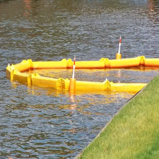
A straight float line can look reassuring while the next reading raises questions. Is the change linked to the work, a tidal shift, another sediment source or the instrument? A useful monitoring plan lets your field team investigate those possibilities and take the required action without guessing.
This guide connects baselines, sampling and response for construction environmental leads and marine project teams. It provides worksheets you can adapt with the responsible reviewer. Project permits, contracts and approved methods determine the actual locations, limits and actions.
Key Takeaways
- Separate the pre-work baseline from the reference reading collected during operations.
- Give every station a purpose, position, sampling depth and flow-direction record.
- Compare readings only under the method and timing rules accepted for the project.
- Preserve original data, required actions and restart approval in one event history.
For the curtain-system context, review our floating silt curtain guide alongside the site’s monitoring documents. Bring the system layout and the sampling plan to the same pre-work discussion so the team can identify missing inputs before fieldwork.
Define What Turbidity Monitoring Must Decide
Write down the acceptance basis
Begin with the documents that control the work. Identify the applicable permit conditions, contract requirements, monitoring plan and approved instrument procedure. Record their revisions so the sampler and reviewer use the same instructions.
Oregon DOT’s December 2024 bulletin illustrates how a named jurisdiction assigns monitoring methods, locations, frequency and response requirements to project documents. Apply the documents governing your own site. ODOT monitoring bulletin
Prepare a decision sheet before the first shift. Complete each field with the responsible environmental lead and resolve conflicting instructions through the project’s review process.
| Decision-sheet field | Information to confirm |
|---|---|
| Controlling basis | Document title, revision and applicable condition |
| Measurement | Approved method, instrument and reported unit |
| Sampling | Station purpose, location, depth, timing and frequency |
| Trigger | Exact comparison rule and action criterion |
| Response | Required controls, notification route and responsible person |
| Recovery | Evidence required for closure and restart authority |
Read the sheet as a shift briefing. Can the sampler find the next due round? Can the person who receives an alert find the required action? Mark each unanswered field and assign it to the responsible reviewer before relying on the sheet in the field.
Keep operational checks and compliance separate
An inside/outside curtain comparison may help investigate containment performance. A compliance point answers the question assigned by the permit. Keep those purposes explicit in the station register, even where an approved plan allows one station to serve multiple purposes.
The Airport Authority Hong Kong’s April 2018 deployment plan includes a dedicated pilot test of curtain efficiency. Its arrangement belongs to that project’s test design. Copying its geometry or intervals into another site’s compliance plan would require a separate justification. A raw difference between two readings cannot establish a universal removal percentage. Airport Authority deployment plan, section 5
Keep selection questions in the turbidity curtain types guide. This monitoring worksheet should identify how observations support decisions while the reviewed system design establishes the curtain’s operating basis.
Establish Baselines and Choose Representative Stations
Separate the baseline campaign from a paired reference
A pre-work baseline describes water conditions before the activity begins. A reference reading taken during the work describes background water at that time. Your plan needs to explain how to use these records together and why the reference suits the comparison.
Record the conditions accompanying the baseline measurements. Water level, current direction, rainfall, nearby activity and the sampling method can help the reviewer interpret variation. A single convenient reading offers limited information about a site with changing flow or sediment sources. Let the project’s environmental lead set the duration and range of conditions needed.
When a later reading rises, did the impact and reference values change together? Check their times and whether the reference stayed outside the work’s influence. Retain the original records so the reviewer can assess what caused the change.
Map stations, depths and current direction
Use a station register and plan view that the sampler can reproduce. Mark the work area, curtain alignment, reference station, operational observation points and designated compliance points. Add observed flow arrows and a sampling-depth reference. This is a field interpretation aid whose geometry must follow the approved site plan.
| Station purpose | Question the record should answer |
|---|---|
| Reference/background | What conditions represent ambient water for this event? |
| Operational impact | What is happening at the selected observation point near the work? |
| Compliance | What does the controlling condition require at this location? |
| Pilot efficiency test | What does the approved paired test design evaluate? |
For each station, record its ID, coordinates or reproducible position, depth datum and safe access arrangements. A label such as upstream needs an accompanying flow observation where the current can reverse. Keep the reviewed station roles available to the crew when conditions change.
Illustrative scenario
A sampler begins a shift with the reference station up-current of the works. The tide turns before the next round. The sampler records the reversal and asks the environmental lead to apply the plan’s station-role rules. The team retains the earlier data with its original station identity and timing.
Depth deserves the same attention as position. State whether sampling depth is measured below the water surface or against another defined datum. Record water level where it affects that interpretation. The silt curtain depth guide helps organize the water-level and curtain-geometry inputs for that discussion.
The Hong Kong pilot protocol illustrates the use of depth-specific observations. Its sampling schedule remains project-specific. Surface appearance alone cannot describe every sampled depth, so ask how your approved programme addresses vertical variation. The drawing, station register and actual field record should all use matching depth references.
Collect Measurements You Can Compare
Match the instrument, method and units
Turbidity is an optical measurement influenced by the particles and measurement method. Two displayed numbers need a documented basis for comparison. Check the method and units before combining a handheld reading, a buoy sensor record and laboratory results.
YSI explains that commonly used nephelometric turbidity units (NTU) and formazin nephelometric units (FNU) identify different optical methods. In its explanation, NTU uses white light and FNU uses near-infrared light, with a 90-degree detection angle. Keep the instrument’s actual method and reported unit in the record. YSI turbidity measurement guide
Total suspended solids (TSS) measures the mass of solids in a volume of water. To convert NTU to mg/L, you need a justified relationship for the site based on suitable paired samples. If the project needs TSS, ask how the team will link laboratory results, optical readings and the accepted relationship.
Record instrument checks and sampling conditions
Prepare the meter using its manufacturer procedure and the approved quality-assurance plan. Confirm the instrument ID, measurement range, required calibration or verification, reference standard and maintenance record. Bring the correct field sheet and a way to retain raw data.
Check optics and sample containers as the procedure requires. Record measurement stability, unusual bubbles, fouling or another condition that could affect a reading. Follow the specified handling and reading sequence for grab samples. For a submersible sensor, confirm its actual position and depth against the station register.
Include repeat or duplicate measurements where the approved quality plan requires them. Record their identities and acceptance checks. Avoid choosing whichever reading is easiest to explain when repeated measurements disagree. Preserve the full sequence and flag the discrepancy for review.
For each grab sample, link the container label to the field sheet’s station, depth and collection time. Follow the approved sample-handling procedure. That link lets the reviewer match a later laboratory result to the intended field observation.
Illustrative scenario
A high reading arrives from a sensor with visible fouling. The team records the value, checks the sensor under its quality procedure and alerts the reviewer.
Required work controls continue during that check. The event record links the original value to all later checks and decisions.
For unattended monitoring, assign responsibility for checking data arrival, power status, maintenance access and alerts. A logger can only support decisions when someone knows how to respond to gaps or suspect values. Test the reporting route as part of the project’s preparation.
Coordinate safe sampling access with the site or marine team. Use the turbidity curtain anchoring guide to organize the mechanical-layout discussion. The approved access arrangements should explain how the sampler reaches the designated position while maintaining safe separation from working equipment and mooring lines.
Interpret Changes and Follow the Approved Response
Use the plan’s comparison and response rules
Use the recorded method, timing, depth and reference conditions to decide whether readings form an acceptable comparison. Where the approved rule uses an increment above background, the calculation is the impact reading minus its accepted paired reference reading. Preserve both raw readings and the calculation inputs.
Check how the plan treats timing offsets, averaging periods, negative differences, missing references and invalid measurements. Record the rule actually applied. If required inputs are missing, identify the gap and follow the relevant response procedure. Filling a spreadsheet cell with an assumed value hides the limitation from the next reviewer.
Build an event matrix from the approved requirements. The worksheet below proposes record categories for that discussion. Populate its action details and responsible names before operations.
| Event | Action to enter from approved plan | Evidence to retain |
|---|---|---|
| Valid reading meets a trigger | Required work control and notification | Raw data, comparison, action time and recipient |
| Visible release or curtain defect | Required inspection and protective response | Location, observations, photos where safe and work activity |
| Suspect instrument reading | Quality checks alongside required work controls | Original value, quality flag, checks and reviewer decision |
| Missing logger or sample record | Specified gap-response and escalation | Missing interval, cause if established and recovery record |
Treat a physical defect as an observation until investigation establishes its contribution to the event. A displaced connection and an elevated reading may occur together. Their timing, location and supporting evidence determine what the reviewer can conclude.
Verify recovery and authorized restart
Illustrative scenario
A valid trigger is reached while a curtain connection problem is suspected. The responsible team implements the required work controls and notifies the named reviewer. Authorized personnel inspect the arrangement, document corrective work and collect the required recovery evidence. The restart decision follows the project’s criteria and assigned authority.
Record the event’s status throughout that sequence. Include who ordered the action, when the work condition changed, which checks followed and which issues remain open. A repeat reading becomes another entry in that history. Keep the original trigger event available for reporting and review.
Repair instructions, stop-work conditions, notification deadlines and restart criteria must come from the controlling requirements. The monitoring record should point to the exact applicable instruction so a person receiving an alert can act promptly.
Before closing the event, reconcile the field sheet, instrument record and work log. Identify any time mismatch or untested explanation. Hand unresolved questions to the named decision-maker with their supporting evidence so the next shift can continue the investigation.
Keep a Turbidity Monitoring Record That Supports Decisions
Retain raw readings and event history
A graph becomes more useful when the reviewer can trace each point to a station, depth, activity and quality check. Keep raw downloads, field sheets, calibration records, marked station plans and response records linked by date and event ID. Preserve corrections with an explanation and retain the original entry.
Use the following blank field groups to build a project log. Copy the fields into the approved reporting format and add any requirements from the controlling documents.
| Field group | Blank entry fields |
|---|---|
| Basis | Plan revision ___ / applicable condition ___ |
| Sample | Station ___ / position ___ / depth and datum ___ |
| Context | Time and zone ___ / flow ___ / weather ___ / activity ___ |
| Measurement | Reading ___ / unit ___ / method ___ / instrument ___ |
| Quality | Calibration record ___ / quality flag ___ / repeat reference ___ |
| Comparison | Paired reference ID ___ / calculation rule ___ / result ___ |
| Response | Decision ___ / action time ___ / responsible person ___ |
| Closure | Recovery evidence ___ / approval reference ___ / open issues ___ |
Leave missing observations visibly marked as gaps and explain how they were handled. Keep notification records with the event so the handoff shows who received the information. Assign ownership to open actions before the shift changes.
At handoff, ask the incoming lead to locate the latest valid reading, any open event and the next required check. Give them the relevant file or sheet references. If a repair is complete but recovery checks remain open, carry that status forward with its named owner.
For the next planning discussion, compare the monitoring record’s mechanical observations with our curtain anchoring guidance. Bring documented layout and operating conditions to the responsible reviewer so the sampling plan and curtain arrangement can be considered together.
Frequently Asked Questions
Where should background samples be taken?
Choose the reference location through the approved monitoring plan so it represents ambient conditions relevant to the impact station. Record its position, depth, timing and flow direction. In tidal water, use the reviewed rules for current reversal and document changes in station role through the designated reviewer.
How often should turbidity be measured?
Use the frequency required by the controlling permit and monitoring plan. Confirm which activities or conditions require extra observations, who reviews logger data and how gaps are handled. Put that schedule in the shift instructions so the sampler can distinguish routine rounds from event-driven measurements and required follow-up.
Can NTU be converted directly to suspended solids?
An NTU reading alone does not establish a TSS concentration in mg/L. The relationship depends on the particles and measurement conditions. Where a conversion is needed, use an accepted site-specific relationship supported by suitable paired laboratory and turbidity data, with its limits documented by the responsible reviewer.
Does clear water prove the curtain is working?
Surface appearance provides an observation that can help an investigation. Assess the curtain using the measurements, locations, depths and criteria required for the project. Record visible plumes or defects alongside the data, and keep visual inspection findings distinct from any conclusion about measured performance or compliance.
When can work restart after an exceedance?
Restart follows the controlling criteria and the decision of the assigned authority. Retain the original event, corrective actions and required recovery checks. The record should identify who authorized restart, when it occurred and what evidence supported that decision, including any remaining conditions the next shift must observe.
Keep your turbidity monitoring basis, station register and response responsibilities together. Before the next shift, use the floating curtain overview to revisit the system context and take open sampling or response questions to the project’s responsible reviewer.