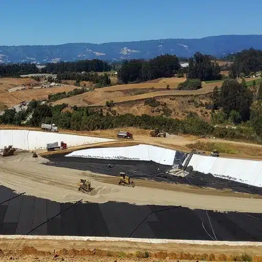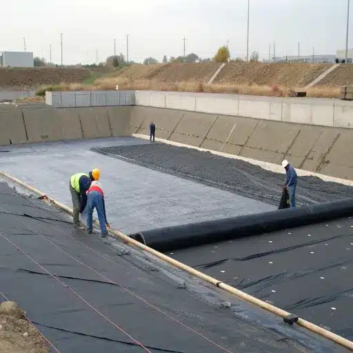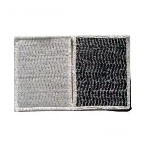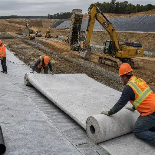
A composite liner system is a containment barrier built from two materials working as one: a geomembrane laid directly over a geosynthetic clay liner (GCL) or compacted clay layer. The geomembrane blocks flow; the clay beneath it seals the defects the geomembrane will inevitably have. Together they leak 25 to 250 times less than either material alone.
That is the theory. In practice, the composite is also the most commonly mis-built liner system in the world, because its entire performance advantage rests on one condition that most installation crews never verify: the geomembrane and the clay must stay in direct, intimate contact.
Picture a containment engineer, Wei, specifying the base liner for a 12-hectare landfill cell. His drawing shows 1.5 mm HDPE over a GCL. His leakage calculation assumes the textbook composite rate.
Halfway through installation, a drainage geonet gets laid between the two layers to solve a slope-water problem. The drawing still says “composite,” but the barrier is no longer one. Wei’s calculation is now off by two orders of magnitude, and nothing on site flagged it.
This guide covers what a composite liner system is and how the GM-over-GCL mechanism works. It also covers the leakage data, the friction and wrinkle limits that decide whether the barrier holds, and 2026 costs.
Key Takeaways
- A composite liner system combines a geomembrane and a clay component acting as one barrier. It is not the same as a double liner, which is two independent liners separated by a leak-detection layer.
- Composite systems leak 0 to 4 L/ha/day, against 100-1,000 L/ha/day for a geomembrane alone and roughly 860 L/ha/day for a GCL alone.
- A GM-GCL composite leaks 2 to 4 times less than a GMB-over-compacted-clay composite at the same defect density.
- Composite action fails if a geotextile, sand, or geonet is placed between the geomembrane and the bentonite. Direct contact is the design.
- Where a geomembrane hole sits directly over a defect in the GCL, leakage can reach 13,000 L/ha/day – the dominant failure mode and the reason defect alignment matters more than defect count.
Building a composite barrier on a compliance-critical site? Request a technical quote and we will match membrane thickness, GCL grade, and friction requirements to your design.
What Is a Composite Liner System?
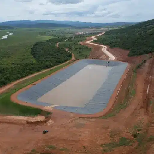
A composite liner system is a multi-layer containment barrier in which a low-permeability geomembrane is placed in direct contact with a clay-based layer – either a geosynthetic clay liner or a compacted clay liner – so the two components act as a single hydraulic barrier rather than two stacked ones.
The definition matters, because the term is routinely misused in two directions.
Composite vs single liner vs double liner
These are three different things, and confusing them leads to real design errors.
- Single liner. One barrier. An unreinforced geomembrane alone, or a clay layer alone.
- Composite liner. Two components in direct contact, forming one barrier. A GMB over a GCL, or a GMB over a CCL.
- Double liner. Two independent liner systems separated by a leachate collection and detection layer. Each of the two liners can itself be a composite.
US EPA guidance is explicit that a composite liner and a double liner are not interchangeable, and Florida’s Department of Environmental Protection makes the same distinction in its liner rules. A double-composite system is therefore a double liner in which both the primary and secondary liners are composites.
If a specification says “composite” and the drawing shows an interposed drainage layer, the drawing is a double liner drawn wrong.
Composite liner system components, top to bottom
A typical single-composite base liner runs in this order:
- Prepared subgrade, compacted and proof-rolled
- Lower hydraulic barrier: GCL or compacted clay liner
- Primary geomembrane, in direct and uniform contact with layer 2
- Protective geotextile or geocomposite cushion
- Leachate collection and removal system (LCRS): gravel or a drainage geonet
A double-composite system inserts a second complete sequence below the first, with a secondary leachate collection and detection layer between them. We cover the GCL-specific build-up in more detail in our guide to types of geosynthetic clay liner.
Why GM over GCL: How the Composite Mechanism Works
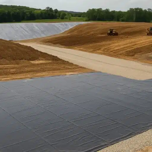
A composite liner system works through two mechanisms at once, and both are easy to state and hard to preserve.
Redundancy and leak-path tortuosity
A geomembrane is a near-perfect barrier across its intact area – HDPE measures around 1×10⁻¹⁴ m/s. Its weakness isn’t permeability but defects: seams, punctures, and wrinkles created during installation.
Research summarised in the Rowe composite-liner literature makes the point. Even with very good field quality assurance, installed geomembranes typically carry 5 to 6 holes per hectare when no location survey is used.
Put a hydrated clay layer directly beneath the membrane and each hole stops being a free path. Water entering the defect must now push sideways through bentonite with a hydraulic conductivity of 5×10⁻⁹ to 10⁻¹¹ cm/s. The leak path becomes tortuous, and the driving head dissipates across a very short distance.
There is a second effect. Sodium bentonite swells on hydration, so a small puncture in the membrane above it tends to self-seal as the clay migrates into the void. One widely cited illustration puts a composite with a 1 cm² hole at roughly 0.2 L/day, against about 200 L/day for the same hole in a geomembrane alone.
The direct-contact requirement
This is the load-bearing condition of the whole design.
EPA testing found the same thing. Effective composite behaviour didn’t occur where the GCL had a geotextile between the defective geomembrane and the bentonite. It occurred only where the geomembrane sat directly on the bentonite.
That finding undoes a lot of otherwise reasonable-looking details:
- A drainage geonet placed between the membrane and the clay to relieve pore pressure destroys the composite.
- A sand blanket used to protect the GCL destroys the composite.
- A carrier geotextile that ends up on the wrong face of the GCL destroys the composite.
In each case the layer is still there. The drawing still reads “composite.” The self-sealing mechanism is bypassed.
There is a documented caveat worth stating plainly. Where contact is poor – because of severe wrinkling, bridging over a geonet, or an interposed layer – a GCL beneath a primary geomembrane may not measurably reduce leakage at all. A designer who assumes the composite benefit without specifying contact quality is relying on a mechanism the project has not built.
For independent installation footage, Naue’s geosynthetics video library shows geomembrane and GCL deployment on real containment projects.
Composite Liner Leakage Rates: What the Data Shows
Leakage is the whole point of a composite liner system, so it is worth being precise about the numbers rather than repeating the usual adjectives. The composite liner leakage rate is the figure regulators care about most.
Leakage comparison by system type
| System | Reported leakage | Basis |
|---|---|---|
| Geomembrane alone | 100-1,000 L/ha/day | Field and calculated, depending on defect density |
| GCL alone | ~860 L/ha/day | Field |
| Composite, GM over GCL | 0-4 L/ha/day | Field |
| Single geomembrane, field average | 55 L/ha/day (1.5-2.0 mm); 325 L/ha/day (2.5 mm) | Field, IAEA data |
Two observations fall out of that table. First, membrane thickness barely changes leakage in a single-liner configuration, because the water goes through defects, not through the membrane. Second, the jump from single to composite is one to two orders of magnitude – which is why regulators treat the composite as a different class of barrier rather than a thicker one.
GMB-GCL vs GMB-CCL: what the numbers say
Most comparisons treat “GCL or compacted clay” as an interchangeable choice for the lower component. The leakage data says otherwise.
Take Rowe’s modelled results: an 11.3 mm hole, a 0.15 m head, five holes per hectare, good contact. A GCL composite leaks 0.36 L/ha/day, against 0.9 L/ha/day for a CCL composite. Under poor contact at the same hole density, the gap widens. The GCL composite leaks 2.0 L/ha/day; the clay composite 8.1 L/ha/day.
Across the modelled range, a GMB-GCL composite leaks roughly two to four times less than a GMB-CCL composite. The clay layer still does work in both cases. But bentonite is the better second barrier. If you’re choosing between them on performance rather than availability, that’s the deciding number.
Our comparison of GCL vs compacted clay liner covers the cost and constructability side.
Aligned defects: the case that dominates all others
The composite’s weakness has an exact shape, and it is worth naming.
A geomembrane hole over intact GCL gives the ~0.4 L/ha/day figure. A hole sitting directly over a defect in the GCL is different. An unsealed seam, a wrinkle that separated the panels, a damaged strip: any of these removes both barriers at the same point.
Reported leakage for aligned defects runs from 13,000 L/ha/day on highly permeable subgrade down to 25-51 L/ha/day on low-permeability subgrade.
Even the best case in that range is roughly 60 times worse than a simple direct-contact hole. The implication for construction quality is direct: the alignment of defects matters more than the number of defects. A liner with 20 scattered holes and no alignment can outperform one with 5 holes where two coincide across the layers.
That’s why GCL panel overlaps must run parallel to the line of maximum slope, with a minimum 12-inch bentonite overlap. It’s also why you shouldn’t place long geomembrane seams directly above GCL seams. And it’s why GCL hydraulic conductivity and its testing matter beyond the headline permeability figure.
Composite Liner Design: Friction, Wrinkles, and Slope Stability
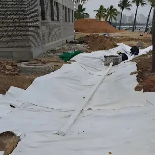
A composite liner system has to survive its own construction and then 30 years of load. Two interface problems decide whether it does.
Interface friction and residual shear strength
The geomembrane-to-GCL interface is typically the weakest interface in a composite system. Peak friction angles for smooth geomembrane against hydrated bentonite can fall to low single figures or low teens in degrees when saturated. Design must not use peak values.
Designers should use residual, post-peak interface friction, because the peak value assumes a mobilised strength that soil-structure interaction will not deliver along a long slip surface. Published practice targets a static factor of safety of 1.5 or better against sliding, using residual values from direct shear testing to ASTM D5321.
Where residual strength is marginal, the standard remedies are:
- Textured geomembrane, which raises interface friction materially against both clay and geotextile. Double-sided textured membrane is common on slopes steeper than 3H:1V.
- Reinforced GCL (needle-punched grades), which raises internal shear resistance so failure does not migrate into the clay core.
- Flatter slopes, or a benched profile that breaks the slip surface.
The Kettleman Hills landfill slope failure in California is the case that forced interface shear into mainstream liner design. It remains the clearest illustration of what happens when a composite is designed on peak strength and built on a long slope. Any design should verify specific friction angles against ASTM D5321 test data for the exact product pairing specified, rather than relying on published ranges.
Wrinkle management thresholds
Wrinkles are not cosmetic. They create targets for holes, they hold the membrane away from the clay so the bentonite cannot seal a defect, and they shorten the path a leak has to travel.
The accepted control figures are:
- Wrinkles limited to less than 8% of the covered area at the time of covering
- Wrinkle height no greater than 50 mm
Both are construction-phase numbers. That means they belong in the specification, not in a post-construction report.
Wrinkle formation depends on installation temperature, time of day, panel deployment direction, and how long the membrane sits exposed. Deploying in the cool part of the day and covering panels promptly isn’t a nicety. It’s what keeps the composite in contact.
Building contact quality into the installation sequence
Three field rules protect the composite mechanism:
- Never place a geonet, sand layer, or drainage composite between the primary geomembrane and the GCL. Route drainage above the membrane or below the GCL, never between them.
- Orient GCL seams parallel to the line of maximum slope, with a minimum 12-inch bentonite overlap, and keep geomembrane seams off the GCL seam lines.
- Cover the GCL the same day it is laid. Installed GCLs should be covered by the geomembrane by end of day and loaded with at least one foot of soil within 60 days, per the New York liner requirements and equivalent state rules.
One operational note that catches out new leak-detection systems: as a landfill cell fills, consolidation water expressed from the GCL can appear in the leak-detection layer and be misread as a leak. Checking the fluid chemistry distinguishes GCL consolidation water from leachate. A team that skips that check can spend a month chasing a leak that does not exist.
Where Composite Liner Systems Are Specified
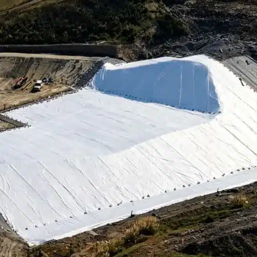
A composite geomembrane liner is the default in three settings, and a fourth is emerging fast.
Landfill base liners and Subtitle D
In the United States, EPA’s municipal solid waste rule under 40 CFR Part 258 (Subtitle D) requires a composite liner: a flexible membrane liner, typically 60 mil (1.5 mm) HDPE, over at least two feet of compacted soil at k ≤ 1×10⁻⁷ cm/s, or an approved equivalent such as a GCL. A single geomembrane is not accepted as a primary MSW liner.
Equivalent composite requirements appear in the EU, Ontario Regulation 232/98, Australia’s ANZECC guidance, and South Africa’s SANS 1526. The compliance pathway is nearly always the same shape: a synthetic membrane plus a low-permeability clay component, in contact. Our GCL landfill liner guide covers how the GCL side is specified differently in base liners and final covers.
Double composite systems
Hazardous waste facilities and several US states go further. New York requires a double composite liner for most landfills. The build-up runs:
- A primary composite of 60 mil HDPE (80 mil in deep-recharge areas) over a GCL
- A secondary leachate collection and detection system, sized for at least 1,000 gallons per acre per day with detection within 24 hours
- A secondary composite of HDPE over two feet of low-permeability soil
The purpose is not redundancy for its own sake. The secondary layer gives you a detection window: leakage through the primary liner shows up in the secondary collection system before it reaches groundwater.
Ponds, reservoirs, and secondary containment
Outside waste containment, composite barriers appear in mine heap leach pads, tailings impoundments, brine ponds, and industrial secondary containment. The design logic is identical, but chemistry changes the specification.
A GCL that performs at 5×10⁻¹¹ m/s in fresh water can lose an order of magnitude under high-calcium or high-salinity leachate. Cation exchange replaces sodium in the bentonite and collapses its swell capacity. Chloride and acidic streams need the same scrutiny.
PFAS and the shift to multi-layer containment
The commercial pressure pushing projects from single to composite and composite to double-composite is now mostly about emerging contaminants.
Research by Rowe and Barakat (2021) modelled PFOS transport beneath a municipal solid waste landfill and found that in most cases aquifer concentrations exceeded regulatory limits under a single liner, leading the authors to recommend that double-liner systems be considered. Per- and polyfluoroalkyl substances do not degrade, are mobile, and are being regulated downward in multiple jurisdictions.
The practical effect on design is straightforward. Advective leakage is only part of the problem. Diffusion through an intact geomembrane carries contaminants through as well.
Adding a second barrier with an adsorptive clay component lengthens breakthrough time rather than just reducing flow. That’s a different argument than the leakage table makes. It’s also why composite specification is rising even where the regulatory minimum hasn’t changed.
Planning a containment system for a regulated facility? Talk to our engineering team about membrane thickness, GCL grade, and chemistry compatibility before you finalise the drawing.
Composite Liner System Cost in 2026
Composite liner pricing follows the material build-up. The premium over a single liner is smaller than most owners expect.
Indicative installed cost bands, 2026
| System | Installed cost (USD/m²) |
|---|---|
| Single HDPE geomembrane | 10-18 |
| Single GCL | 6-12 |
| Composite, HDPE + GCL | 15-25 |
| Composite, HDPE + 0.6 m compacted clay | 18-30 |
| Double composite (hazardous waste class) | 30-50 |
A composite system typically carries a $3-8/m² premium (30-50%) over a single-layer liner. On a hazard-class facility the double-composite premium is larger because it is a second complete liner, not a second component.
A line-item build-up for a mid-size MSW cell looks roughly like this: subgrade preparation $3/m², 1.5 mm geomembrane $7/m², GCL $7/m², protective geotextile $2/m², drainage geonet $4/m², welding labour $6/m², third-party CQA $1.50/m², and survey $0.50/m². That totals about $31/m² before contingency, or roughly $36/m² with 15% added.
Those figures are indicative only. Actual pricing moves with HDPE resin prices, freight and haul distance, local labour rates, site conditions such as rock or groundwater, and the thickness and texture your design demands. Textured membrane on slopes can add 20-40% over smooth.
A site-specific quotation is the only number worth designing to. Our breakdown of GCL cost per square meter covers the clay component in more detail.
The economics that actually decide it
Upfront cost rarely settles the choice. One developer value-engineered the bentonite out of a 10-hectare industrial cell to save about $4/m² – roughly $400,000 across the footprint.
The saving lasted two years. The single geomembrane carried more defects than the design assumed, and with no clay layer beneath it there was nothing to arrest them. Detection monitoring caught the first exceedance three quarters later, and the retrofit required excavating and relining a cell that was already partly filled. The composite they skipped would have cost a fraction of that relining.
That is not an argument that every project needs a composite. It is an argument that the number to compare is 30-year cost of containment, not day-one cost per square meter.
Frequently Asked Questions
What is the difference between a composite liner and a double liner?
A composite liner is two materials – typically a geomembrane and a GCL or clay layer – in direct contact, acting as one barrier. A double liner is two separate liner systems with a leachate collection and leak-detection layer between them. A double liner can be built from two composites, which is a double-composite system.
Does a GCL reduce leakage under a geomembrane?
Yes, but only when the geomembrane sits in direct contact with the bentonite. EPA testing found no effective composite behaviour where a geotextile separated the geomembrane from the bentonite. With good contact, a GM-over-GCL composite leaks roughly 0.4 L/ha/day at typical defect densities, against 100-1,000 L/ha/day for the geomembrane alone.
How thick should the HDPE geomembrane be in a composite liner?
60 mil (1.5 mm) is the standard minimum for a municipal solid waste base liner, and some jurisdictions require 80 mil in sensitive areas. Thickness has little effect on leakage through defects, so the choice is driven by puncture resistance, stress-cracking resistance, and regulatory minimums rather than by permeability.
Can a GCL replace the compacted clay layer in a landfill liner?
Often yes, through an equivalency demonstration. A GCL must provide flow control equal to or better than a compacted soil liner at 1×10⁻⁷ cm/s or less, and its bentonite must show chemical and physical stability against the specific waste stream. Cation exchange is the usual reason an equivalency argument fails.
Is a composite liner system worth the extra cost?
It depends on the consequence of failure. The composite premium is typically $3-8/m², while remediation and penalties on a leaking cell can run tens of millions. Where the contained material is inert and the site is unconstrained, a single liner may be defensible. Where it is not, the composite is the cheaper option over the life of the facility.
Conclusion
A composite liner system delivers performance no single material can reach, and it does so through a mechanism that is easy to specify and easy to accidentally destroy.
The essentials:
- Composite means one barrier, not two. Two components in direct contact. A double liner is a different system with a detection layer between two independent liners.
- Contact quality is the design. No geonet, sand, or geotextile between the geomembrane and the bentonite. If contact is compromised, the composite benefit can disappear entirely.
- GM over GCL outperforms GM over compacted clay, leaking two to four times less at the same defect density.
- Defect alignment beats defect count. An aligned geomembrane hole over a GCL defect can leak 13,000 L/ha/day, so seam layout and panel orientation are performance decisions.
- Friction and wrinkles decide whether it lasts. Design on residual interface strength, target a factor of safety of 1.5, and hold wrinkles under 8% of covered area.
Every one of those points is settled at the specification and installation stage. Once the cell is filled, none of them can be fixed.
If you are specifying a composite liner system, our technical team can match membrane thickness, GCL grade, bentonite chemistry, and interface friction requirements to your project conditions, and supply both components from one place with the documentation your submittal needs. Request a technical quote and we will respond with a specification recommendation for your site.