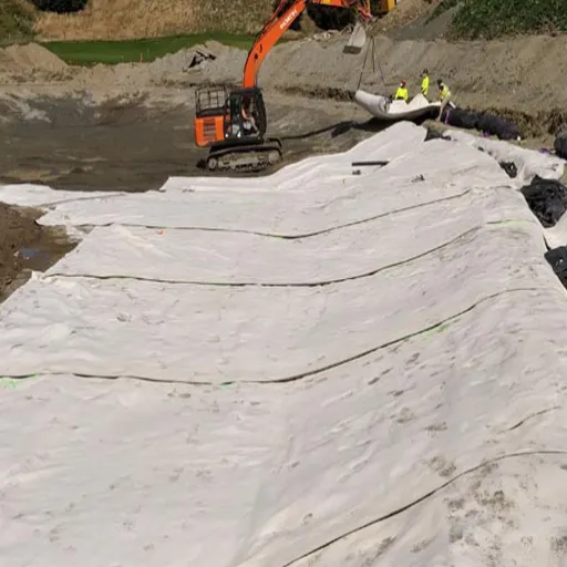
A geogrid works by interlocking with aggregate or soil through its open apertures, restraining lateral movement, and carrying tensile load so the reinforced layer behaves as a stiffer composite. The mechanism depends on aperture-to-particle compatibility, rib geometry, and confinement, not on tensile strength alone.
That is the short answer to how does geogrid work. The longer answer depends on scale.
At the particle scale, soil and aggregate transfer stress into the grid. At the layer scale, confinement creates a mechanically stabilized layer. At the structure scale, the grid carries tensile load across a potential failure surface.
Most explanations stop at “the soil locks into the holes.” That is accurate but incomplete. It does not tell an engineer which aperture to specify or why two grids with the same strength perform differently.
This guide walks through the full load-transfer chain. You will see how aggregate strike-through, passive bearing, and skin friction move stress into the grid. You will see how confinement turns a loose base into a stiffer composite.
You will also see how to verify performance with the right test methods. Our broader geogrid soil reinforcement guide covers design and application selection, while this article focuses on the mechanism itself.
Key Takeaways
- A geogrid works through mechanical interlock and passive bearing, not by acting like a flat reinforcing sheet.
- Aperture-to-aggregate compatibility is decisive: a practical target is A/D50 ≈ 1.25–2.5 for well-graded base material.
- At layer scale, interlock and confinement can deliver TBR up to 8.9, BCR up to 64%, and a 322% gain in effective base modulus in modeled pavement studies.
- The tensioned membrane effect is secondary; it requires large deformation and matters mainly on unpaved or very soft ground.
- Verify performance with product-specific ASTM D6637, D6706, D5321, and D5262 data, not a generic “high strength” claim.
What Does a Geogrid Actually Do?
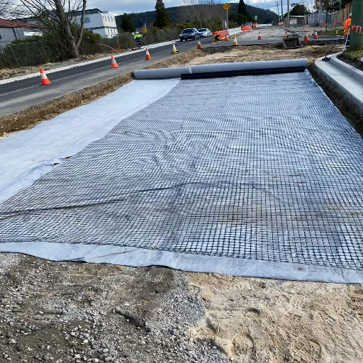
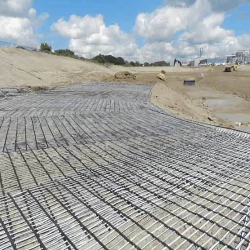
A geogrid is a polymer grid with open apertures and high-tensile ribs. It works by locking aggregate or soil into its openings, restraining lateral movement, and carrying tensile load, which turns a loose layer into a stiffer composite.
The key word is composite. The grid does not replace the soil. It changes how the soil behaves under load. That principle explains how geogrid works in every application that follows.
Stabilization and reinforcement are different functions
ISO 10318-1:2015 separates two functions that buyers often conflate. Stabilization is the confinement of aggregate through interlock, which inhibits particle movement under load. Reinforcement is the tensile member carrying load within a soil mass.
A biaxial grid in a road base is mostly stabilizing. A uniaxial grid in a retaining wall is reinforcing. The same polymer can do both, but the design checks, test data, and installation details differ.
EOTA Report TR 41 makes the same point. Stabilization comes from the mechanical confinement effect of a stiff grid, not from tensile strength alone. That is why a grid with high ultimate strength can still perform poorly when its apertures do not match the fill.
The grid needs the fill
Without compatible aggregate, proper compaction, and confinement, the apertures do nothing. A geogrid on a clean, hard surface with no cover is just a sheet of polymer.
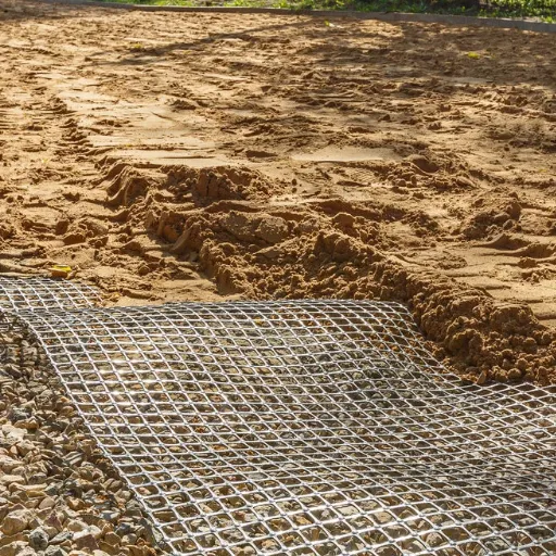
The mechanism starts when particles seat into the openings and the layer is compacted around them.
If you already have a gradation curve and a CBR value, our engineers can check aperture compatibility before you specify. Contact engineering support with your soil data and load conditions.
How Does Geogrid Work at the Particle Scale?
At the particle scale, three paths transfer load from soil to grid: aggregate strike-through, passive bearing on transverse ribs, and skin friction along the rib surfaces. The interaction model then quantifies how efficiently those paths work.
Aggregate strike-through and aperture interlock
When aggregate is placed and compacted over a grid, particles partially penetrate the apertures and seat against the ribs. Under load, the grid restrains those particles. The layer can no longer spread laterally as a loose mass.
Interlock is a system property. It depends on the grid, the aggregate, the compaction, and the stress state together. Change one and performance changes.
Aperture-to-aggregate compatibility is the first control. For well-graded base aggregate, a practical target is:
A/D50 ≈ 1.25–2.5
Below roughly 0.9–1.0, particles bridge the opening. Interlock is weak and behavior becomes friction-dominated. Above roughly 3.5, bearing and confinement efficiency decline.
Published optima range widely, from about 1.2 to 5.4, depending on whether the descriptor is D50, D90, or Dmax. Confirm the choice with interface shear (ASTM D5321) or pullout (ASTM D6706) testing for the actual grid and aggregate pair.
Angular, well-graded aggregate develops stronger interlock than rounded or single-sized material. Compaction matters too. Particles must seat into the apertures, not merely sit on top.
Consider Daniel, a project engineer in Queensland. He specified a biaxial grid by tensile strength alone. The grid’s 60 mm apertures were more than five times the site’s single-sized 10 mm aggregate, so particles passed through instead of locking.
The base rutted within weeks of opening to traffic. Re-testing with an aperture matched to the gradation solved the problem, but the first repair cost more than the entire grid supply.
Aperture selection deserves its own decision process. Our geogrid aperture size and aggregate interlock guide turns gradation data into a selection table.
Passive bearing on transverse ribs
As the soil mass tries to move laterally, particles bear against the faces of the transverse ribs. This passive bearing is the defining mechanical advantage of a geogrid over a flat geotextile. The grid provides physical bearing surfaces, not just surface friction.
Transverse members dominate pullout resistance. Rib thickness relative to grain size matters. Interlocking becomes significant when the rib-thickness-to-mean-grain-size ratio is small, roughly below 3 in the cited literature. Bearing capacity in front of a rib scales with Nq, a function of the soil friction angle.
This is why two grids with the same ultimate tensile strength can behave differently. One may have thicker ribs, a stiffer junction, or a geometry that engages the aggregate more effectively.
Skin friction along the ribs
Interface shear along the top and bottom rib surfaces adds resistance. It depends on normal stress, rib roughness, soil type, and moisture.
For geogrids, friction is secondary to interlock and passive bearing. For geotextiles, it is the only load-transfer path. That difference explains much of the performance gap between the two materials.
The interaction model: Ci, F*, and alpha
Designers quantify soil–geogrid interaction with three parameters.
The coefficient of interaction (Ci) compares interface shear strength to soil shear strength:
Ci = tan δ / tan φ
Here, δ is the soil–geogrid interface friction angle and φ is the soil friction angle. Ci is generally below 1 for smooth inclusions but can exceed 1 for geogrids because passive bearing adds resistance beyond simple friction.
The pullout resistance factor (F*) converts friction angle into a design value. FHWA guidance uses approximately 0.8 tan φ for geogrids in granular soil and about two-thirds tan φ for geotextiles.
The scale-effect factor (alpha) corrects for non-uniform stress transfer along an extensible reinforcement. Typical values are about 0.8 for geogrids, 0.6 for geotextiles, and 1.0 for inextensible reinforcement such as steel.
The normalized pullout form for grids and sheets is:
Pr = 2 F alpha σv Le*
Here, σv is effective vertical stress and Le is embedment length. The full design treatment, including pullout safety factors and anchorage length, belongs in our geogrid pullout resistance guide.
The teaching point is simple. A geogrid’s advantage is geometric and mechanical, not just higher tensile strength. Interlock and passive bearing change the interaction, and that changes the composite.
| Mechanism | Physical action | Key parameter | Design meaning |
|---|---|---|---|
| Aggregate interlock | Particles seat in apertures and are restrained by ribs | A/D50 ≈ 1.25–2.5 | Select grid and fill together |
| Passive bearing | Soil bears against transverse rib faces | Rib geometry, Nq, F* | Main advantage over geotextile |
| Skin friction | Interface shear along rib surfaces | δ, Ci | Secondary for geogrids |
| Load spreading | Composite layer distributes stress | Stiffness, layer modulus | Raises bearing capacity, cuts rutting |
How Does Geogrid Work at the Layer Scale?
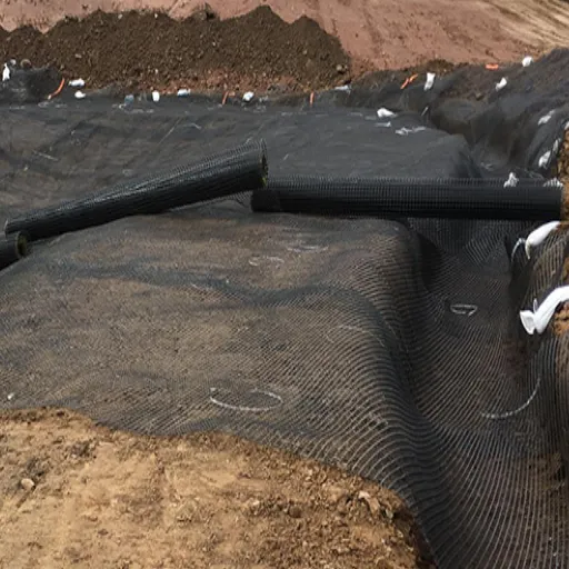
At the layer scale, individual particle restraint becomes a structural effect. The grid and aggregate act together as a mechanically stabilized layer (MSL).
Confinement and the mechanically stabilized layer
Interlocked aggregate cannot spread laterally, so the layer stays thick and stiff under load. Confinement raises the aggregate’s shear strength and resilient modulus compared with the unreinforced layer.
This is the main reason geogrids reduce rutting on roads and working platforms. The mechanism is not that the grid holds up the load like a bridge. It is that the grid keeps the aggregate from spreading, so the aggregate continues to do its job.
Load spreading and bearing capacity
The stabilized layer distributes wheel or structural loads over a wider area, reducing stress intensity on the subgrade. On weak ground, this is the snowshoe effect. The reinforced layer spreads load and reduces differential settlement.
The effect increases as the subgrade gets weaker. That is why geogrids show their greatest benefit on low-CBR ground and their smallest benefit on stiff, well-drained subgrades.
Quantified performance
A 2023 modeling study by Abu-Farsakh, Zadehmohamad, and Voyiadjis, published in Infrastructures, evaluated a single geosynthetic layer at the base–subgrade interface. The analysis found a traffic benefit ratio (TBR) up to 8.9, a base effective resilient modulus increase up to 322%, and a base course reduction (BCR) up to 64%.
The benefits increased with geosynthetic tensile stiffness and rutting target. They decreased with subgrade stiffness and peaked at a base thickness of about 25.4 cm (10 in). Those conditions matter. A 64% base reduction headline is not a universal guarantee.
Full-scale USACE ERDC unpaved pavement testing also reported a 64% reduction in surface rutting for specific geogrid sections. Treat that as a test-specific result, not a property of every grid on every site.
Consider Priya, a procurement manager in Nairobi comparing two biaxial grids with the same declared tensile strength. One supplier provided junction efficiency, rib profile, and aperture dimensions. The other provided only a strength value.
A field trial on a low-CBR haul road showed the first grid reduced rut depth by roughly a third after 5,000 equivalent axle passes. The second grid performed close to the unreinforced section. The price difference was 8%. The performance difference was not close.
The tensioned membrane effect is secondary
The tensioned membrane effect is often presented as the main mechanism. It is not. At large deformation, a geogrid can sag into a curved membrane and contribute a vertical component of tension. That requires enough rutting to mobilize curvature and anchorage beyond the loaded area.
Research by Giroud concludes the effect is relatively small. It applies mainly to channelized traffic on unsurfaced roads where large rutting is tolerable. For paved-road stabilization, lateral restraint and interlock dominate. Our tensioned membrane effect explainer covers the evidence and the debate.
Why Do Geogrids Reinforce Better Than Geotextiles and Steel?
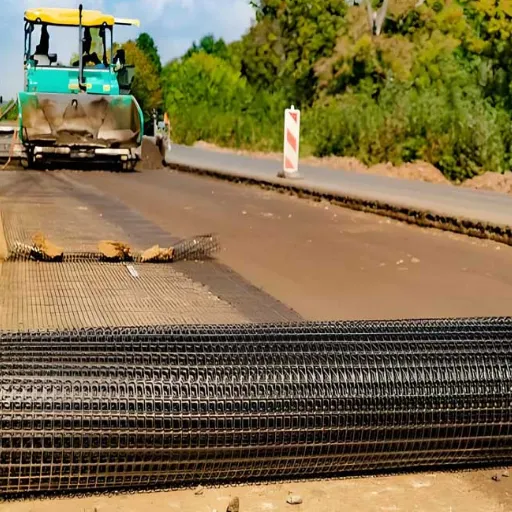
A geotextile is a planar sheet. Load transfers by friction along its surface, and the sheet can limit aggregate-to-aggregate contact. A geogrid has apertures, so particles meet through the openings and the ribs provide passive bearing.
That geometry explains the parameter gap. F* is about 0.8 tan φ for geogrids versus about two-thirds tan φ for geotextiles, and alpha is about 0.8 versus 0.6. It also explains why Ci can exceed 1 for a geogrid but rarely does for a flat sheet.
The comparison is not absolute. Geotextiles are the right choice for separation, filtration, and drainage. On fine-grained subgrades, the best system often combines a geotextile separator with a geogrid reinforcement layer.
Steel reinforcement is a different trade-off. Steel strips or mesh offer high stiffness and well-established design methods, but they are vulnerable to corrosion and require careful backfill chemistry and cover. Geogrids are polymeric, resist corrosion, and are lighter to handle, but their design must account for creep and installation damage. Our geogrid vs steel reinforcement comparison covers the life-cycle and design differences.
How Does the Mechanism Change by Application?
The same grid can stabilize, reinforce, or do both. The dominant geogrid mechanism depends on where it sits and what the structure needs.
| Application | Dominant mechanism | Design relies on |
|---|---|---|
| Road base / subgrade | Interlock, lateral restraint, load spreading | Aperture compatibility, CBR, base thickness |
| Retaining / MSE wall | Tensile reinforcement and pullout resistance | Long-term design strength, embedment, facing connection |
| Slope / embankment | Tensile reinforcement and pullout; membrane at failure | Slip surface, anchorage, drainage |
| Soft ground / working platform | Bearing capacity and load spreading; membrane at large rut | Subgrade strength, stiffness, separation layer |
In a road base, the grid is usually placed at the subgrade–base interface or within the base. Interlock and confinement do most of the work.
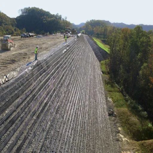
In a retaining wall, the grid extends into the backfill and connects to the facing. Pullout resistance and long-term strength govern. On a slope, the grid crosses the potential slip surface and anchors beyond it.
A single geogrid specification is not enough. The application determines which mechanism must be mobilized.
What Breaks the Mechanism, and How Do You Verify Performance?
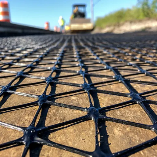
Four problems account for most failures of the geogrid mechanism:
- Wrong aperture size. Too small, and aggregate bridges the opening. Too large, and confinement is lost. Interlock never develops.
- Poor fill or compaction. Particles do not seat in the apertures, so the composite behaves like loose fill.
- Insufficient embedment or anchorage. The grid pulls out before its tensile strength is mobilized.
- Installation damage, UV exposure, or creep. Ribs and junctions are damaged during fill placement, exposed grid degrades, and sustained load causes time-dependent strain.
Consider Luis, a site engineer in Peru. His crew placed a geogrid over a soft subgrade, then pushed aggregate into place with a tracked loader. The grid wrinkled and was damaged at the junctions.
The design assumed full tensile strength, but the installed grid had lost a significant fraction of it before the first lift was compacted. A tensioned installation and a protective lift would have avoided the repair.
Verification starts with product-specific data. Ask for ASTM D6637 tensile properties, ASTM D6706 pullout resistance, ASTM D5321 direct shear and interface friction, and ASTM D5262 creep data for reinforcement applications.
Then check aperture dimensions, rib profile, junction efficiency, polymer type, and UV stabilization. Confirm the design basis against ISO 10318-1 definitions and a recognized design method such as FHWA-NHI-10-024 or AASHTO LRFD.
Our geogrid specifications and test standards guide explains how to read these values and compare suppliers.
Frequently Asked Questions
How does geogrid work in road construction?
It interlocks with aggregate in the base layer, restrains lateral spreading, and spreads wheel loads over a wider subgrade area. The result is a stiffer composite layer that reduces rutting and can allow a thinner base when the design conditions support it.
Does geogrid need to be stretched or tensioned?
Stabilization geogrids are laid flat and pulled taut to remove wrinkles. They do not need high tension because interlock develops during aggregate placement and compaction. Reinforcement geogrids in walls and slopes are tensioned and anchored according to the design.
How does geogrid increase bearing capacity?
By confining aggregate and spreading load over a wider area, the grid reduces stress intensity on the subgrade and raises the effective bearing capacity of the reinforced layer. The benefit is largest on weak, low-CBR ground.
What aperture size should a geogrid have?
For well-graded aggregate, target A/D50 ≈ 1.25–2.5, avoiding ratios below about 0.9 or above about 3.5. Confirm the choice with interface shear or pullout testing for the actual grid and aggregate.
Can geogrid work without aggregate or soil cover?
No. The grid needs fill to interlock with and confine. Without cover, it also loses UV protection and may be damaged during construction.
Is geogrid better than geotextile?
For reinforcement and stabilization, geogrids generally transfer load more efficiently because of aperture interlock and passive bearing. Geotextiles remain better for separation, filtration, and drainage. Many projects use both.
Conclusion
How does geogrid work? It changes how soil particles interact under load. Aggregate locks into the apertures, bears against the ribs, and is restrained from spreading. At layer scale, that confinement produces a stiffer composite that spreads load and reduces rutting.
The practical lessons are straightforward:
- Match the aperture to the aggregate, because A/D50 is a system decision rather than a product label.
- Expect the largest benefit on weak subgrades, with the right fill and compaction.
- Treat the tensioned membrane effect as secondary, not the main mechanism.
- Verify tensile, pullout, shear, and creep data before you approve a supplier.
- Select the product for the application, because stabilization and reinforcement are different jobs.
If you are specifying a geogrid for a road, wall, slope, or working platform, send our engineering team the gradation, CBR, and load data. We will help you match the mechanism to the material. Request a technical quote or contact our engineering support for a project-specific recommendation.