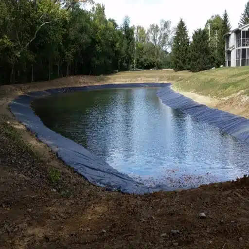
Geogrid soil reinforcement is the use of a high-tensile-strength polymer grid, embedded in soil and interlocked with aggregate, to carry the tensile loads that soil alone cannot sustain. The soil supplies compressive strength, the geogrid supplies the tensile strength, and together they behave as a single composite mass with higher bearing capacity, steeper stable slopes, and less deformation under traffic.
That one-sentence answer hides the engineering that makes it work, and that is where projects succeed or fail. Manufacturers are quick to say a geogrid reinforces soil. Almost none publish the numbers that decide whether your project actually needs reinforcement, how strong the grid must be, or how long it will last underground.
The result is two expensive mistakes. Some teams over-specify reinforcement on sites that only needed a separation geotextile, wasting budget on material they never required. Others under-build on weak, low-CBR subgrades that quietly rut and fail within the first season.
This guide is the engineering reference for geogrid soil reinforcement. It covers how geogrids reinforce soil at the mechanism level, the design parameters that govern performance, when reinforcement is genuinely required, the field data that justifies the cost, durability and creep, failure modes, and how to specify and buy with confidence. By the end you will be able to make a data-backed reinforcement decision for your next earthworks, road, or retaining project.
Key Takeaways
- Geogrid soil reinforcement works through four mechanisms: aggregate interlock, lateral restraint, load distribution, and, at large deformation, a tensioned membrane effect. Pullout resistance ties them together.
- Reinforcement is required when soil must carry tensile load (walls, slopes) or when a weak subgrade with a CBR below roughly 4 to 8 must be stabilized under traffic. Below CBR 3 you also need a geotextile separator.
- Design is governed by long-term design strength (LTDS = UTS / (RF_ID x RF_CR x RF_D)), which is typically 33 to 50% of the ultimate tensile strength, plus pullout and aperture compatibility.
- Full-scale data shows base course reductions up to 64%, traffic benefit ratios up to 8.9x, and rutting life extended from about 20 to about 540 load cycles.
- Choose uniaxial geogrids for walls and slopes, biaxial for road bases, and triaxial for heavy pavements and haul roads; each is specified by tensile strength class in kN/m, not by catalog price.
If you want the broader product picture first, our complete geogrid guide to types, applications, and selection covers the whole family. This article goes deeper into the reinforcement mechanics and design.
What Is Geogrid Soil Reinforcement?
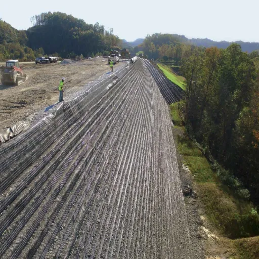
Geogrid soil reinforcement is the use of a high-tensile-strength polymer grid, embedded in soil and interlocked with aggregate, to carry tensile loads that soil alone cannot sustain. The soil provides compressive strength, the geogrid provides tensile strength, and together they behave as a composite mass with higher bearing capacity, slope stability, and resistance to deformation.
That definition is worth unpacking because it explains everything that follows. Unreinforced soil is strong in compression but weak in tension. A vertical cut or a steep slope fails because the soil cannot resist the tensile stresses that develop along a potential slip surface. A geogrid supplies exactly that missing tensile component.
Geogrids are made from polypropylene (PP), polyester (PET), or high-density polyethylene (HDPE). They come in three geometries, each matched to a different job:
- Uniaxial geogrids carry high strength in one direction and are built for retaining walls, steep slopes, and embankments.
- Biaxial geogrids deliver roughly equal strength in two directions and are the workhorse for road bases and subgrade stabilization.
- Triaxial geogrids spread load in three directions and perform best under heavy, multidirectional traffic.
The practical payoff is measurable. Unreinforced fill slopes are limited to about a 2:1 (horizontal to vertical) angle before they become unstable. Reinforced slopes can be built at 1.5:1, 1:1, or even steeper on tight sites. That is why a 20-foot slope that would need 40 feet of horizontal footprint at 2:1 can fit into roughly 20 feet once a geogrid is added.
To put the scale in context, geogrid soil reinforcement underpins a global market worth roughly 1.4 to 1.5 billion dollars in 2026, with road construction accounting for about 48% of demand. The engineering, not the commodity, is what delivers the performance.
For the underlying theory of how the grid and the soil interact, the mechanism deep-dive in our how geogrid reinforces soil guide walks through the soil-geogrid interaction model in detail.
How Does a Geogrid Reinforce Soil?
Four mechanisms explain how a geogrid reinforces soil, and they work together rather than in isolation. A fifth, pullout resistance, describes how the grid anchors itself in the soil so the other four can act.
Mechanical Interlock and Passive Bearing
Aggregate particles drop through the grid apertures and bear against the transverse ribs. This passive bearing resistance is the defining advantage of a geogrid over a flat geotextile, because the ribs physically lock onto the aggregate. Interlock works best when the aperture is roughly 1.2 to 1.6 times the nominal aggregate size, so particles partially strike through and get gripped. Selecting that aperture ratio is a decision in itself, and our geogrid aperture size and aggregate interlock guide turns it into a simple selection table.
Lateral Restraint and Confinement
Friction along the rib surfaces restrains lateral spreading of the granular layer under load. Confined aggregate behaves like a much stiffer material, forming what engineers call a mechanically stabilized layer (MSL). This confinement is the main reason geogrids cut rutting on roads and working platforms.
Load Distribution and Composite Action
The grid spreads wheel loads over a wider subgrade area, reducing vertical stress intensity and subgrade pressure. Combined with compaction, the geogrid plus aggregate behaves as a single structural unit rather than a loose layer sitting on weak soil. That load-spreading behavior is what raises the effective bearing capacity of a marginal subgrade, and we quantify it in the geogrid bearing capacity guide.
Tensioned Membrane Effect
At very large deformation, such as ruts around 100 mm deep, the geogrid stretches and acts like a tensioned membrane, distributing load across the span. This effect matters mainly for unpaved and temporary roads where deep ruts are tolerable before surfacing. It is also the most misunderstood mechanism in the industry, so we treat it honestly and source-cite both sides in our tensile membrane effect explainer.
Pullout Resistance
For the grid to reinforce anything, it must stay anchored in the soil. Pullout resistance has two components: skin friction along the rib surfaces and passive bearing on the transverse ribs. Designers quantify it with the pullout resistance factor F* and the scale-effect factor, and our geogrid pullout resistance and coefficient of interaction guide covers the equations and design values.
The numbers behind all of this are well established. A 2023 modeling study that fed full-scale results into the MEPDG pavement framework found a single geosynthetic layer delivered a base course reduction up to 64%, a traffic benefit ratio up to 8.9 times, and a 322% gain in effective base resilient modulus. Geogrids outperformed geotextiles in that study because of the aggregate interlock inside their apertures.
Soft CTA: Not sure which reinforcement mechanism your project actually needs? Our engineers provide tailored recommendations based on your soil report and loading. Talk to engineering support and get a straight answer.
Soil Reinforcement vs. Soil Stabilization: What’s the Difference?
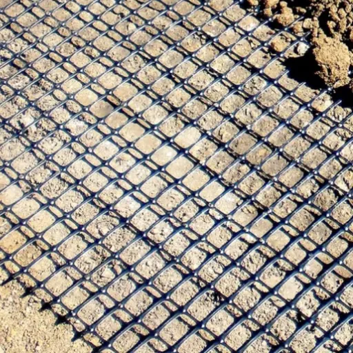
The two terms are often used interchangeably, but they describe different load conditions, and the distinction changes your specification.
Soil reinforcement uses the stress-strain behavior of the geosynthetic to improve the soil mass. It matters where continuous loads translate into tensile stress on the grid, such as retaining walls and steep slopes, where the geogrid crosses potential failure planes.
Soil stabilization improves the mechanical behavior of an unbound granular material by confining particles and reducing lateral movement. It matters on roads and pavements, where a stiffer stabilized layer resists rutting under repeated wheel loads.
In practice, the same geogrid can do both, depending on where you place it and how it is loaded. Many projects genuinely need both: a reinforced slope built over a stabilized subgrade, or a geogrid paired with a geotextile separator on a soft, fine-grained subgrade. Continuous or tensile loading calls for reinforcement; intermittent or confining loading calls for stabilization.
The comparison in our geogrid vs geotextile guide explains exactly when each product carries the load and when you need them layered together.
Now consider a real case that shows why this distinction matters. A highway contractor working over expansive clay in Texas kept seeing rutting after every rain during construction. He had been using a nonwoven geotextile for separation, which controlled fines migration but did nothing to confine the aggregate. Adding a single biaxial geogrid at the subgrade interface let him cut the aggregate base from 18 inches to 12 inches, eliminate the rutting, and finish the season on schedule. Separation was the problem he thought he had. Reinforcement was the problem he actually had.
When Do You Need Geogrid Reinforcement?
The most practical trigger is subgrade strength, measured by the California Bearing Ratio (CBR). The US Army Corps of Engineers guidance (ETL 1110-1-189) and Indian highways guidance (IRC SP 49:2014) give clear thresholds.
| Subgrade CBR | Primary Function | Recommended System |
|---|---|---|
| Below 0.5 | Mechanical subgrade stabilization | Design a construction platform so equipment can work |
| 0.5 to 4.0 | Stabilization plus base reinforcement | Geogrid reinforcement; add a geotextile separator on fine-grained subgrades (CBR at or below 4) |
| Below 3.0 | Separation also required | Geogrid plus nonwoven geotextile, or a factory-bonded geocomposite |
| Below 1.0 | Very soft ground | Double-layer geogrid for “floating road” construction, such as over peat |
| 4.0 to 8.0 | Base reinforcement primary | Geogrid at the base-subgrade interface; separator generally not needed |
| Above 8.0 | Base reinforcement | Empirical thickness charts not valid; design from test sections |
Two points deserve emphasis. First, a geogrid does not filter. It reinforces, but it lets fines migrate, so on soft clays and silts below about CBR 3 you pair it with a separation geotextile or a geocomposite. Second, reinforcement is not always needed. On competent subgrades above roughly CBR 8, on shallow temporary slopes, or on low walls under about 1.2 m (4 ft), a geogrid adds little value.
The full treatment of very soft sites, from peat to saturated clays, lives in our geogrid for soft ground and subgrade stabilization guide.
Quantified Performance: What the Data Shows
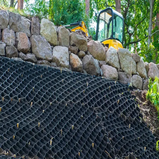
Reinforcement claims sound good in a brochure, so here is the evidence from full-scale testing and published studies.
- Base course reduction (BCR): up to 64% with a single geosynthetic layer in the 2023 MEPDG study. Triaxial geogrid field trials computed reductions of 21.6 to 44.8%, and full-scale UNLV testing cut an unreinforced 406 mm base by 26% (biaxial) and 45% (triaxial).
- Traffic benefit ratio (TBR): up to 8.9 times in modeling. Full-scale sections recorded TBR values of 3, 7.5, 3, and 4 at 6 mm of rutting.
- Rutting resistance: in one Naue field test, an unreinforced base reached 75 mm of rutting after about 20 load cycles, while the geogrid-reinforced section lasted roughly 540 cycles.
- Aggregate savings: road and platform projects typically reduce base thickness by 30 to 50%. A mine haul road in Australia fitted with heavy-duty biaxial geogrid eliminated rutting entirely and cut base thickness by half.
- CBR improvement: IRC SP 49 reports reinforcement factors of 2.0 to 3.0 in sub-base layers.
- Factor of safety in slopes: a 2026 parametric study using PLAXIS 2D and SLOPE/W found that geogrid inclusion raised the factor of safety by 4% to 268%, depending on slope geometry and reinforcement configuration.
- Carbon savings: studies cited in market analysis show geogrid-reinforced base layers cut material haulage by 28 to 45%, saving 58 to 85 tonnes of CO2 equivalent per kilometer on two-lane highways.
The pattern is consistent: the softer the subgrade, the larger the benefit. Benefits shrink as the subgrade stiffens, which is exactly why the CBR threshold table above matters. For the raw specification numbers that let you compare suppliers, our geogrid specifications and ASTM standards guide lists typical tensile classes and the test methods to ask for.
There is also a cautionary data point. A review of 20 case histories by Allen and colleagues found that reinforcement is typically over-specified by 1.5 to 4 times what long-term stability actually requires. The biggest waste in this industry is not under-design. It is paying for material a site never needed.
Design Parameters That Govern Performance
If you take one section from this guide, make it this one. The parameters below separate a geogrid that performs for a century from one that fails in a season.
Ultimate vs. Long-Term Design Strength
Geogrids are rated in kilonewtons per meter (kN/m), usually at 2% and 5% strain. Do not specify off the ultimate tensile strength (UTS) alone. The long-term design strength (LTDS) accounts for installation damage, creep, and chemical and biological degradation.
Reduction Factors
The governing relationship is simple:
LTDS = UTS / (RF_ID x RF_CR x RF_D)
Where RF_ID is the installation-damage reduction factor (typically 1.1 to 2.0), RF_CR is the creep reduction factor (1.5 to 5.0, depending on the polymer), and RF_D is the durability reduction factor for chemical and biological effects (1.0 to 1.5). The result is that LTDS typically lands at 33 to 50% of the UTS rating. Our reinforced soil design guide works through the full factor-of-safety framework, resistance factors, and a complete worked example.
Pullout Resistance and Coefficient of Interaction
In walls and slopes, the grid must extend far enough beyond the failure plane to resist pullout. For geogrids in granular soil, FHWA guidance commonly takes the pullout resistance factor F* as 0.8 times the tangent of the soil friction angle, compared with about two-thirds for geotextiles. The scale-effect factor runs near 1.0 for inextensible reinforcement and 0.6 to 0.8 for extensible reinforcement, and the coefficient of interaction (Ci) ranges roughly 0.60 to 1.00 depending on soil type and normal stress. Pullout is measured by ASTM D6706. The full design equations are in our geogrid pullout resistance guide.
Aperture and Junction Efficiency
Interlock only works when the aggregate is the right size for the apertures. As a rule of thumb, aperture should run about 1.2 to 1.6 times the nominal particle size, and junction efficiency should be 90% or better. Verify both on the datasheet before you approve a roll.
| Parameter | What it controls | Typical value | Test method |
|---|---|---|---|
| Ultimate tensile strength | Peak load capacity | Product-specific (kN/m) | ASTM D6637 |
| Long-term design strength | Allowable load over design life | 33 to 50% of UTS | AASHTO R 69 |
| Installation damage factor | Handling and compaction loss | 1.1 to 2.0 | ASTM D6637 |
| Creep reduction factor | Time-dependent loss | 1.5 to 5.0 | ASTM D5262 / D6992 |
| Durability factor | Chemical and biological loss | 1.0 to 1.5 | ASTM D7238 |
| Aperture ratio | Aggregate interlock | 1.2 to 1.6x nominal size | Physical |
| Junction efficiency | Load transfer across ribs | 90 to 95% or better | ASTM D6637 |
| Pullout resistance factor F* | Anchorage capacity | 0.8 tan(phi) granular | ASTM D6706 |
With the numbers in hand, the geogrid aperture size guide and the reinforced soil design guide show how to turn them into a specification.
Geogrid Reinforcement by Application
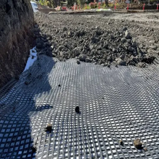
The same material behaves differently across applications because the loading, the failure mode, and the relevant design check all change.
Roads, Subgrades and Working Platforms
Place a biaxial or triaxial geogrid at the subgrade-base interface, spread aggregate, and compact. The grid confines the aggregate, which cuts rutting, reduces differential settlement, and typically lowers base thickness by 30 to 50%. A minimum granular base of 0.15 to 0.20 m is a prerequisite for the reinforcement to mobilize. Our geogrid for road base guide covers design and installation for driveways, access roads, and heavy haul routes.
Retaining and MSE Walls
Uniaxial geogrid layers extend horizontally into compacted backfill behind the wall face. The grid carries the tensile forces that hold the reinforced soil mass together, which lets segmental walls reach heights conventional cantilever walls cannot match without massive footings. Typical vertical spacing runs 8 to 24 inches, with embedment of at least 0.7 times the wall height per AASHTO guidance. Our uniaxial geogrid for retaining and MSE walls guide covers design, connections, and facing details.
Slopes and Embankments
On slopes, geogrid layers cross the potential slip surface and supply tensile resistance that lets you build steeper than the unreinforced limit. Current design guidance suggests geogrid length roughly equal to slope height for slopes of 4 to 8 m, and about 1.2 times the height for slopes of 8 to 16 m. Vertical spacing runs 0.5 to 1.0 m on milder 30 to 45 degree slopes and 0.25 to 0.5 m on steeper 45 to 75 degree slopes. On embankments over soft ground, basal reinforcement reduces lateral spreading and settlement during construction. Our geogrid slope stabilization guide details the design approach.
Soft Ground, Haul Roads and Railways
On very low CBR sites, a geogrid inside a crushed-rock pad creates a stiff working surface that spreads heavy equipment loads and stops machines from sinking. For extreme conditions, such as haul roads across peat, double-layer systems come into play. Rail ballast reinforcement follows similar load-spreading logic. When cellular confinement is the better answer, our geogrid vs geocell comparison helps you decide which reinforcement product suits the soil.
Expansive Soils and Seismic Regions
On expansive clays, geogrids limit swelling strain and release lateral swelling pressure, improving resistance to shear failure through wet and dry cycles. In seismic zones, wrapped-face and composite reinforcement systems change how reinforced structures respond to cyclic loading. That specialist topic is covered in our seismic design of geogrid-reinforced soil structures guide.
Geogrid vs. Alternative Reinforcement Systems
A geogrid is one option among several, and the right choice depends on the failure mode you are addressing.
Geogrid vs. geotextile. A geogrid carries tensile load through interlock and is far stiffer than a geotextile. A geotextile handles separation, filtration, and drainage. They are not competitors so much as members of a layered system. Our geogrid vs geotextile guide lays out the full decision.
Geogrid vs. geocell. Geogrids are planar and two-dimensional; geocells are three-dimensional cellular confinement that trap fill in individual pockets. Geocells often win for fine-grained soils and very steep slope faces; geogrids win for road bases and reinforced soil structures.
Geogrid vs. steel reinforcement. Steel strips and wire mesh are inextensible, while polymer geogrids are extensible, and the two produce different earth-pressure states (K_0 versus K_a). Steel is strong but corrodes; geogrid resists corrosion but is subject to creep and UV limits. Our geogrid vs steel reinforcement comparison covers where each system wins.
Durability, Creep and Service Life
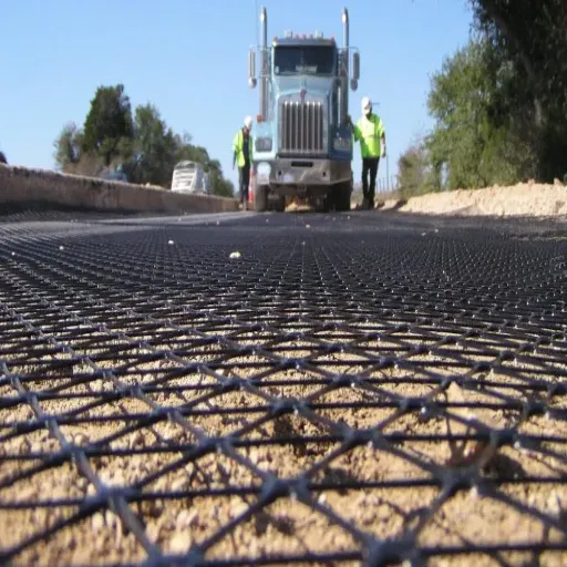
A reinforcement that loses strength over 75 years is a liability, not an asset. Durability is where the LTDS calculation gets its meaning.
Creep and Long-Term Design Strength
Creep is the gradual extension of a polymer under sustained load. Designers handle it with the creep reduction factor RF_CR, derived from long-term laboratory tests. The classic method is ASTM D5262, a conventional 10,000-hour test extrapolated to the design life, while ASTM D6992 uses the accelerated stepped-isothermal method. Confined in-soil testing usually shows less creep than in-air testing.
Values are product-specific, and that matters. Published data shows creep reduction factors of about 1.45 for some polyester grids tested to ASTM D5262, and 2.6 to 2.7 for certain high-strength geogrids extrapolated to a 120-year design life at 20 degrees Celsius. If you are specifying a PET grid, expect the lowest creep factors; PP behaves worst. The physics, the test extrapolation, and the polymer-by-polymer numbers are broken down in our geogrid creep and long-term design strength guide.
Environmental Durability and Service Life
Buried geogrids do not see sunlight, but they do see soil chemistry, moisture, and mechanical handling. Quality HDPE and PET geogrids are engineered for 75 to 120 years underground. Two durability controls matter most in practice: carbon-black content for UV stability, and the exposure window during installation, typically 7 to 15 days before the grid must be covered. The full picture, including UV, chemical, and biological resistance and how each folds into the reduction-factor framework, is in our geogrid durability and service life guide.
Failure Modes and How to Avoid Them
Reinforced soil structures rarely fail because the concept is wrong. They fail for predictable, avoidable reasons.
- Wrong aperture versus aggregate. If the apertures are far larger or smaller than the aggregate, interlock never develops and the grid slides instead of confining.
- Insufficient anchorage length. A grid that does not extend far enough beyond the failure plane pulls out instead of carrying load.
- Inadequate cover. Less than the specified aggregate cover exposes the grid to puncture and UV degradation.
- Installation damage. Over-compaction or track traffic directly on exposed grid tears ribs and reduces strength, which is exactly what RF_ID accounts for.
- Connection and junction failure. In MSE walls, the face connection and junction strength can govern before the grid body does.
- Drainage omission. Trapped water raises pore pressures and undermines the whole system.
The over-design counterpoint belongs here too. The same Allen review that found 1.5 to 4 times over-specification is a reminder that failure prevention and cost control pull in the same direction when you specify from engineering data. For a forensic walk-through of real failures and the lessons they teach, see our geogrid failure modes and case studies guide.
How to Specify and Buy Geogrid Reinforcement
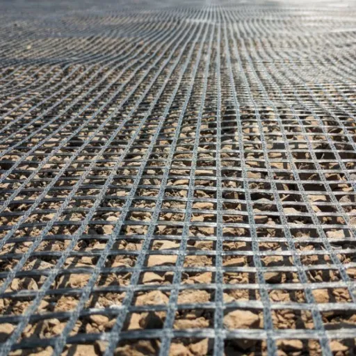
Follow this sequence and you will avoid both over-specification and under-building.
- Confirm the need. Run the CBR framework above. If separation is all you need, use a geotextile.
- Define the load. Traffic class, wall height, slope angle, and surcharge all drive the strength class.
- Pick the type. Uniaxial for walls and slopes, biaxial for road bases, triaxial for heavy pavements and haul roads.
- Specify the strength class in kN/m. Compare suppliers on LTDS, not just UTS, and ask for the 2% and 5% strain values.
- Check aperture and junction efficiency. Match apertures to your aggregate and require 90% or better junction efficiency.
- Verify quality. Ask for ASTM test reports, ISO 9001 manufacturing certification, and carbon-black content for UV stability.
- Compare total installed cost. Roll price is only part of the story. Include aggregate savings, installation time, and expected service life.
Want a worked example that follows the whole process from soil report to purchase order? Our how to choose geogrid guide walks through a full project.
Frequently Asked Questions
What is geogrid soil reinforcement?
Geogrid soil reinforcement is the use of a high-tensile polymer grid, interlocked with soil and aggregate, to carry the tensile loads soil cannot sustain alone. The soil and grid act as a composite mass with higher bearing capacity and stability than unreinforced soil.
How does a geogrid reinforce soil?
A geogrid reinforces soil through aggregate interlock, lateral restraint, load distribution, and, at large deformation, a tensioned membrane effect. Aggregate particles bear against the transverse ribs, confining the granular layer and letting the grid carry tensile loads. The full mechanism breakdown is in our how geogrid reinforces soil guide.
What is the coefficient of interaction for geogrid?
The coefficient of interaction (Ci) describes pullout efficiency at the soil-geogrid interface, typically 0.60 to 1.00 depending on soil type and normal stress. For geogrids in granular soil, FHWA design often uses a pullout resistance factor F* of 0.8 times the tangent of the friction angle. See our geogrid pullout resistance guide for design values.
What reduction factors apply to geogrid design?
LTDS = UTS / (RF_ID x RF_CR x RF_D). Installation damage runs 1.1 to 2.0, creep runs 1.5 to 5.0 depending on polymer, and durability runs 1.0 to 1.5. Because of these factors, long-term design strength is typically 33 to 50% of the ultimate tensile strength.
When is geogrid reinforcement required?
Reinforcement is required when soil must carry tensile load, such as in retaining walls and steep slopes, or when a weak subgrade (roughly CBR below 4 to 8) must carry traffic. Below about CBR 3, combine the geogrid with a geotextile separator to stop fines migration.
Does a geogrid stop settling?
A geogrid reduces and evens out settlement by distributing load and confining the aggregate, but it does not stop consolidation settlement of deep soft soils. On those sites, combine reinforcement with other ground-improvement measures.
How long does geogrid last underground?
Quality HDPE and PET geogrids are engineered for 75 to 120 years underground. Longevity depends on carbon-black content, correct cover within the exposure window, and the durability reduction factor applied in design. Our geogrid service life guide covers the details.
Conclusion
Geogrid soil reinforcement is an engineered solution, not a commodity add-on. It works through interlock, lateral restraint, and load distribution. It is genuinely required when soil must carry tensile load or when a low-CBR subgrade must support traffic. And the data shows measurable payback: base course reductions up to 64%, traffic benefit ratios up to 8.9 times, and rutting life extended from roughly 20 to 540 cycles.
The practical takeaways are simple. Match the geogrid type to the job, uniaxial for walls and slopes, biaxial for road bases, triaxial for heavy pavements. Specify by long-term design strength, aperture compatibility, and junction efficiency, not by brochure numbers. And use the CBR framework to decide whether you need geogrid soil reinforcement at all, because the biggest waste in this industry is paying for a material a site never needed.
If you are specifying a project and want an independent read on the geogrid type, strength class, and quantity, our engineering team supplies export-ready geogrids with technical consultation and flexible order terms. Start with our complete geogrid guide, then request a technical quote with your soil report and loading details.