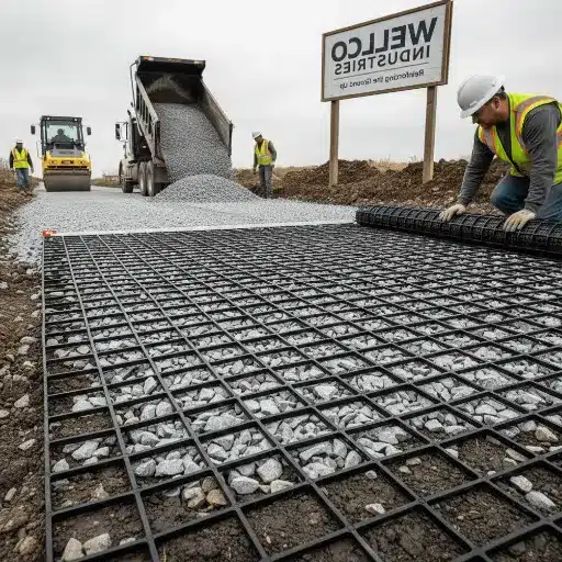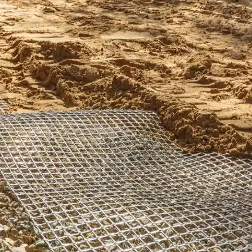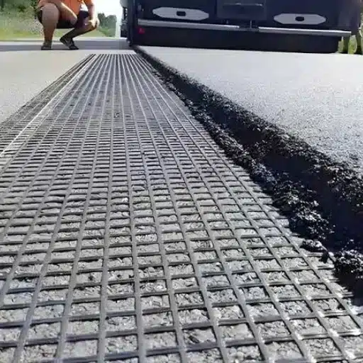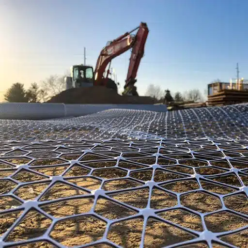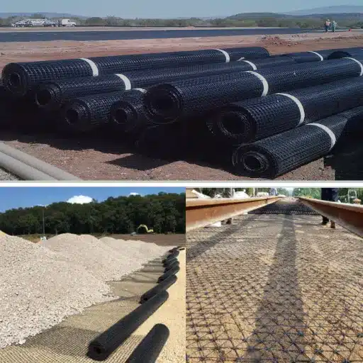
Geogrid slope stabilization works by placing horizontal layers of uniaxial geogrid in compacted fill lifts, so the soil and grid behave as one reinforced composite that resists internal sliding and can stand far steeper than unreinforced ground. Reach for it when you must build or repair a slope or embankment beyond roughly 2H:1V, when you have room for a reinforced zone behind the face, and when the problem is internal stability rather than deep-seated global failure. Get those conditions wrong and the grid does nothing; get them right and it replaces a concrete wall at a fraction of the cost.
Consider a wind-farm access embankment we were asked about. The contractor had built the haul road up to a 1.5H:1V batter over soft, wet ground, and after two weeks of rain a 15 m section of the face slumped, taking a drainage channel with it. The fix everyone reached for first, a concrete wall, meant importing foundations and weeks of formwork and curing on ground that could barely carry a truck. Layering a uniaxial geogrid into the rebuilt fill, wrapped at the face, held the batter, let the crew reuse on-site material, and kept the site open.
By the end of this guide you will know how geogrid reinforces a slope, how to pick a system by slope angle, how engineers actually design it to BS 8006-1, FHWA GEC 11, and EBGEO, what the stability and cost numbers look like, how wrapped-face and veneer construction differ, how to install it so it survives, and how it compares with a concrete wall, soil nailing, and riprap. For the wider product background, see our complete geogrid guide to types, applications, and selection.
Key Takeaways
- Geogrid slope stabilization reinforces the fill so it resists internal sliding; it does not stop surface erosion, which needs a separate geomat, geocell, or vegetation layer.
- Unreinforced soil generally holds about 2H:1V (roughly 27°); geogrid lets you build steeper, from veneer reinforcement on flatter slopes to wrapped-face slopes near 70° and near-vertical walls to about 85°.
- Design is an output of stability analysis to a recognized code (BS 8006-1, FHWA GEC 11, EBGEO), not a catalog value: layer spacing commonly falls at 0.3–0.6 m, with FHWA capping grid spacing at 800 mm.
- Reinforcement lifts the factor of safety sharply and cuts settlement; measured gains run from marginal values near 1.0–1.3 up into the 1.7–2.8 range, with settlement reductions of roughly 22% to 65%.
- Geogrid slopes typically cost far less than concrete walls (one DOT study: about $112 per lineal foot versus $204–220), tolerate settlement and seismic movement, and can be vegetated, but they cannot fix poor drainage or global instability.
What Is Geogrid Slope Stabilization?
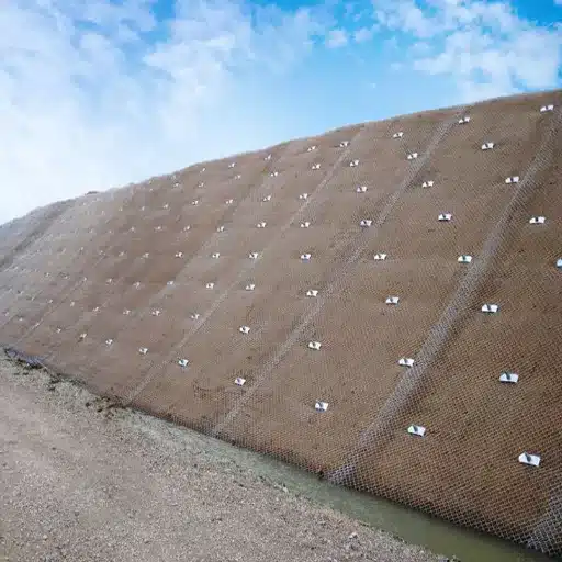
Geogrid slope stabilization is the use of horizontal layers of uniaxial geogrid, placed in compacted fill lifts, to reinforce a slope or embankment so it acts as a single soil-geogrid composite that resists internal sliding and can be built much steeper than unreinforced soil.
The mechanism is straightforward. A potential slip surface tries to move downslope, but it must now cut through grid layers embedded in the fill. The grid resists that movement in tension, while the soil resists it in friction and interlock. The result is a reinforced mass that behaves like a coherent block rather than a pile of loose material.
This is the same family of behavior engineers use in mechanically stabilized earth (MSE) walls, but the geometry differs. A reinforced slope is a sloped mass that typically climbs at 1.5H:1V to 1H:1V or steeper; an MSE wall is near-vertical and carries a structural facing. When a reinforced slope becomes steep enough, the design effectively becomes a reinforced-soil wall, and the analysis shifts to wall methods.
Internal Sliding vs Surface Erosion: Two Problems, Two Solutions
A slope fails in two unrelated ways, and confusing them is the most common specification mistake in this field.
Internal stability failure happens when a mass of soil slides along a deep surface because the fill has no tensile strength. This is what buried geogrid reinforcement fixes.
Surface, or face, failure happens when rain, runoff, and wind strip topsoil and fines off the face before vegetation establishes. A buried grid layer does nothing about this, and a surface mat does nothing about internal sliding.
The practical consequence is that steep, durable slopes usually need both, chosen independently: reinforcement inside the fill, protection on the surface. A three-dimensional reinforced geomat filled with topsoil and seeded, or a geocell where flow concentrates, handles the face. We cover that product family in our guide to geotextile erosion control for slope faces, which is a different set of materials from structural reinforcement.
If you have been searching for “geogrid erosion control,” that phrase actually points at the surface-protection family, not at reinforcement. Decide which failure you are solving before you order anything.
Not sure which failure you’re looking at? Send us your site conditions and our engineers will tell you what the slope actually needs.
How Geogrid Reinforces a Slope
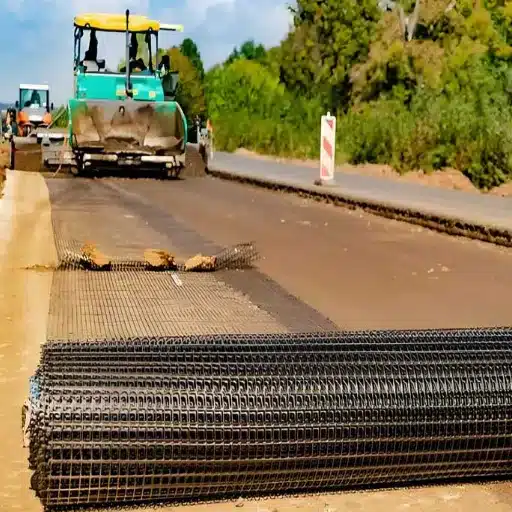
Geogrid slope reinforcement works because a slip surface has to cut the grid, and the grid resists in tension while the soil resists in friction. Load transfers from the moving soil into the grid through interlock at the apertures, and the grid carries it back into the stable fill behind the slip surface. To understand the underlying mechanics in more detail, see our guide to how geogrid soil reinforcement works.
Tension in a slope acts mainly in one direction, down the face. That makes uniaxial geogrid for slopes the correct default, laid with its strength, or machine, direction running perpendicular to the face. Biaxial grid, which carries strength in two directions, belongs under roads and platforms where wheel loads arrive from multiple directions. What slope angles each system supports is covered in the next section, as is the point where we hand off to uniaxial geogrid for retaining walls and MSE walls.
Material choice follows the same logic. For ordinary granular fill, punched-and-drawn polypropylene uniaxial geogrid, typically spanning 60 to 300 kN/m of machine-direction strength, is the workhorse. Polyester geogrids suit irregular faces and tight radii because they drape and wrap a lift well, and they publish long-term design strength against a stated design life. HDPE grids are the choice where published creep and durability data are required. Effective reinforcement generally needs high tensile stiffness, often above about 260 kN/m, so a soft, low-modulus grid gives little benefit regardless of its ultimate strength.
What Slope Angle Can Geogrid Reinforce?
Unreinforced soil will hold roughly 2H:1V, near 27°, and flatter. Geogrid lets you go steeper, but the system changes as the angle increases, and steep slope reinforcement demands progressively more grid. The table below is the quick-selection version engineers and buyers can use to frame a design conversation.
| Slope angle or condition | Recommended system | Typical face treatment |
|---|---|---|
| Flatter than about 2H:1V (≤ ~27°), no internal issue | Surface protection only, no structural grid | Geomat, geocell, or hydroseeding |
| About 2H:1V to 1.5H:1V, modest steepening | Veneer reinforcement (short grid layers, terminated near the face) | Topsoil plus erosion mat |
| About 1.5H:1V to 1H:1V and steeper | Wrapped-face (wrap-around) reinforced slope | Wrapped vegetated face or geomat |
| Near-vertical, about 70° to 85° | Reinforced-soil wall or MSE with structural facing | Block, panel, or steel mesh facing |
Indicative only. Final geometry, layer spacing, embedment length, and required strength are design outputs of a stability analysis, not catalog values.
The angle bands come from practice and should be read as capability ranges, not guarantees. What actually decides the achievable angle is the soil strength, the groundwater and pore-pressure regime, the layer spacing, the reinforcement strength, and the surcharge and seismic demand acting on the slope, never the grid alone.
How Geogrid Slope Stabilization Is Designed
Design is an output of stability analysis, not a product selection. Layer spacing, embedment length, and required grid strength all fall out of that analysis, which is why any supplier who quotes a fixed spacing from a catalog is guessing.
Engineers work to recognized codes. In the United Kingdom and much of the Commonwealth, that is BS 8006-1:2010+A1:2016, the code of practice for strengthened and reinforced soils. In the United States, highway applications follow the Federal Highway Administration manuals, FHWA NHI-10-024 and NHI-10-025, published under GEC 11 as the guidance for MSE walls and reinforced soil slopes, available through the FHWA geotechnical publications library. Germany uses EBGEO, and Australia uses AS 4678.
The analysis checks three failure modes: internal, where the slip surface passes through the reinforced zone; external, where it passes behind or beneath it; and compound, where it crosses both. Designers then verify global stability, sliding, bearing, settlement, and seismic performance with a pseudo-static check. Most methods are limit-equilibrium and allowable-stress based; LRFD approaches are not yet fully developed for reinforced soil slopes, which is worth knowing when you compare specifications.
Practical values seen across projects sit in a narrow band. Vertical layer spacing commonly falls between 0.3 m and 0.6 m, with fill placed and compacted in around 60 cm lifts. FHWA and AASHTO cap grid spacing at 800 mm, while BS 8006-1 sets no such fixed cap. Reinforcement length is expressed as a length-to-height ratio and read from design charts against the slope angle and soil friction angle.
What Geogrid Slope Stabilization Delivers: The Numbers
The performance case for geogrid slope stabilization is well documented, and the figures are worth knowing before you commit.
- Factor of safety. A clay-shale platform study found the unreinforced factor of safety sat at 1.30, the minimum threshold of the local standard, and rose to 1.82 once geogrid was added. Maximum deformation fell from 0.25 m to 0.14 m, a 41% reduction, and settlement dropped from 5.2 cm in 38 days to 3 cm in 64 days.
- Spacing sensitivity. On a soft clay slope at 1V:1.5H, the unreinforced factor of safety of 1.25 increased to 2.15, 2.74, and 2.83 as grid spacing tightened from 3 m to 2 m to 1 m, a 72% to 126% gain. On loose sand, the same spacings lifted a marginal 1.05 to 1.25, 1.40, and 1.71.
- Settlement control. Geogrid combined with jet-grout columns on a road embankment over soft subsoil produced a 220% increase in factor of safety and a 65% reduction in total settlement. A gabion-faced reinforced wall study found that optimizing geogrid spacing cut vertical settlement by about 22%. You can read the full study in the International Journal of Geosynthetics and Ground Engineering.
- Landslide repair. On the E75 motorway, flexible polyester geogrids with design strengths of 34 to 64 kN/m and lengths of 9 to 12 m stabilized a landslide; the flexible solution cut construction time by 30% to 50% and cost by more than 20% against a stiff-grid alternative. Flexibility was the deciding factor on settlement-prone ground.
- Very soft ground. Embankments on the Amsterdam A2/A9 project reached 12 m high at slopes up to 65° over very soft soil, with undrained safety factors around 1.06 to 1.31. The flexible wraparound construction followed differential settlements of up to 2.5%.
Cost follows the same pattern. An Iowa DOT study of a reinforced slope reported a final construction cost of about $112 per lineal foot, against preliminary estimates of $204 to $220 per lineal foot for concrete, gabion, and sheet-pile alternatives, with little or no maintenance expected. Vendor figures run higher on the savings side, from 30% to 70% against concrete walls, so treat those as indicative. On soft or unstable ground, our guide to geogrid for soft ground and subgrade stabilization covers the reinforcing-over-weak-subgrade case in full.
Wrapped Face vs Veneer vs Wall
How the reinforcement terminates at the face defines the construction method, and it is where a lot of projects go wrong.
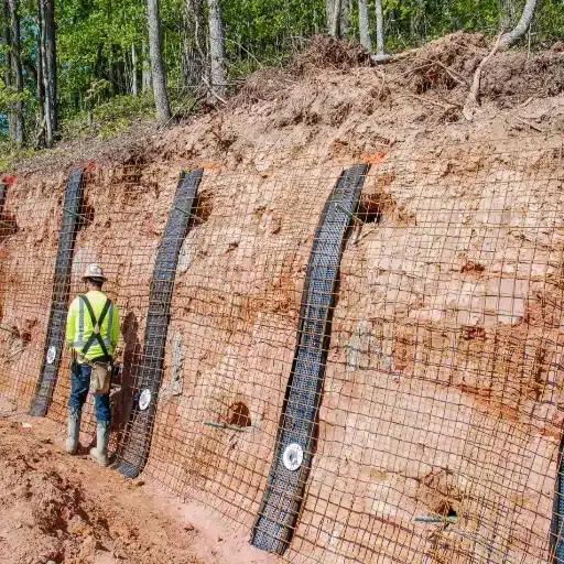
In wrapped face geogrid construction, also called wrap-around, the top of each geogrid layer is turned back over the compacted lift and buried in the fill above. This confines the soil at the edge, exactly where reinforcement is weakest and where compaction plant cannot reach properly, and it gives topsoil and seed something to sit in instead of sliding off. Wrapped faces allow the steepest reinforced slopes and a vegetated finish.
In veneer reinforcement, grid layers run through the fill and terminate close to or at the face, on slopes up to about 45°. The face is then dressed and protected separately with topsoil and an erosion mat. It is simpler and cheaper than wrapping, and it is the right choice where the slope does not need to be steep.
In a reinforced-soil or MSE wall, the geometry is near-vertical and the grid connects to a structural facing of blocks, panels, or steel mesh. The design shifts to wall methods and facing-connection checks, which we cover in the dedicated retaining wall guide linked above.
How to Install Geogrid for Slope Stabilization
Installation determines whether the design is realized or quietly undermined. The sequence below reflects field practice; for the general protocol across applications, see our full geogrid installation guide.
- Prepare and prove the subgrade. Clear debris, roots, and large rocks, then grade and compact to the design angle. Proof-roll the surface, undercut soft spots, and replace them with compacted granular fill. Make sure drainage will not pond under the grid.
- Cut an anchor trench at the crest. This keyway acts as a deadman anchor that holds tension and blocks surface water from seeping behind the face. Dimensions are design-driven; common practice falls around 300 to 450 mm deep and back from the edge, while demanding specifications call for at least 610 mm. Round the corners, remove loose material, extend the grid down the front and across the base, then backfill and compact.
- Lay the geogrid from the crest downward, with the strength direction perpendicular to the face. Pull it taut and flat, remove every wrinkle, and avoid over-tensioning, which can reduce load-bearing capacity.
- Handle overlaps to the specification. Across the roll width, overlap roughly 150 to 300 mm, or butt panels with ties where the spec allows. In the main reinforcement direction, use continuous panels: most specifications forbid laps there, because plastic-to-plastic overlap has reduced friction. Where a splice is unavoidable it must be high-efficiency, around 75% or better, with soil placed between the layers.
- Pin and stake as you go. Use a staggered grid at roughly 1.0 to 1.5 m each way, tightening the spacing and adding pins at overlaps, curves, and steeper faces. Steel pins or rebar of 12 to 16 mm with plate caps work on soft ground. Pin through the apertures, never through the ribs.
- Wrap the face on wrapped-face designs. Turn each layer’s top back over the compacted lift and bury it before starting the next lift.
- Place fill in thin lifts. Spread lifts of about 150 to 200 mm in the direction the reinforcement was laid, compact each one, and keep at least 150 mm of cover over the grid before any plant runs on it. Never drive tracked equipment on exposed geogrid.
- Install drainage and face protection. Put a separator and drainage layer behind the reinforced zone, then apply the geomat, geocell, or hydroseeding on the face and maintain the vegetation that follows.
The most common mistakes are the same everywhere: skipping compaction, getting overlaps or orientation wrong, and running equipment on bare grid.
Geogrid vs Concrete Retaining Wall, Soil Nail, and Riprap
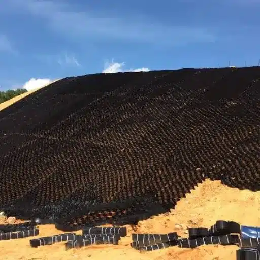
Geogrid is one tool among several, and picking correctly matters more than optimizing the wrong choice.
A geogrid reinforced slope is flexible, tolerates differential settlement and seismic movement, uses on-site or varied fill, typically needs no structural foundation, can be vegetated, and usually costs less and builds faster. Its constraint is space: it needs room behind the face for the reinforced zone, and it depends on good drainage.
A concrete retaining wall occupies a smaller footprint but is rigid, tolerates settlement poorly, needs a substantial foundation, and requires formwork and curing. It costs more and takes longer, and it is the right answer where space behind the face is genuinely unavailable.
Soil nailing and ground anchors excel on existing steep cuts and rock, where reinforcement must be installed into the ground rather than built up with fill. They involve drilling and grouting and suit retained cut faces more than new embankments.
Riprap and other surface protection only address erosion on the face. They do nothing for internal stability.
The honest limitation is this: geogrid reinforces the soil that is there. It does not fix deep-seated global failure, high pore pressures, or poor drainage. If global stability or groundwater is the real problem, fix that first with drainage, a toe berm, piles, or anchors, and use geogrid for the reinforcement layer.
How to Buy Geogrid for Slope Projects
Specify the system, not just the material. Send your supplier the slope angle and height, the soil parameters, the groundwater and pore-pressure regime, the surcharge and seismic demand, the required factor of safety, and the intended layer spacing and face treatment. A supplier who can talk through those inputs is a partner; one who quotes a roll size is not.
Then verify quality. Ask for wide-width tensile test reports to ASTM D6637, strength values at 2% and 5% strain, and a documented long-term design strength rather than an ultimate strength. Confirm the creep reduction factor, the junction efficiency, which should be around 90% or higher, and that the aperture is matched to the fill so interlock actually develops. Check the polymer type, the carbon-black or UV data, and ISO 9001 certification. The IGS specification document for reinforced soil structures is a useful reference for what a complete specification should contain.
For buyers sourcing internationally, also weigh export capability, flexible minimum order quantities suited to slope and embankment-scale projects, and access to technical consultation on the section design. Shanxi Shengxing supplies geogrid for slopes and earthworks alongside woven and nonwoven geotextiles for the drainage and separation layers, with custom specifications and engineering support.
Ready to specify your slope? Send your section details and soil data to our engineering team for a tailored quotation.
Frequently Asked Questions
How do you stabilize a slope with geogrid?
You bury horizontal layers of uniaxial geogrid in compacted fill lifts, with the strength direction running down the face, and either wrap each layer at the face or terminate it with a protected face. The grid and soil then act as one reinforced mass that resists internal sliding.
What slope angle can geogrid reinforce?
Unreinforced soil holds about 2H:1V, near 27°. Geogrid allows steeper construction: veneer reinforcement to roughly 45°, wrapped-face slopes to about 70°, and near-vertical walls to around 85°. The achievable angle depends on soil strength, groundwater, spacing, grid strength, and loads.
Uniaxial or biaxial geogrid for slopes?
Use uniaxial. Tension in a slope acts mainly in one direction, down the face, so a single-direction grid aligned perpendicular to the face is correct. Biaxial grid suits roads and platforms where loads arrive from multiple directions.
How far should geogrid extend into a slope?
Embedment length is a design output, expressed as a length-to-height ratio read from stability charts against the slope angle and soil friction angle. It is not a fixed number, so it must come from the analysis, typically 0.6 to 1.0 times the height or more.
What spacing should geogrid layers be on a slope?
Vertical spacing commonly falls between 0.3 m and 0.6 m, with fill placed in lifts of around 60 cm. FHWA and AASHTO limit grid spacing to 800 mm, while BS 8006-1 sets no fixed cap. Tighter spacing raises the factor of safety.
How deep should the anchor trench be at the crest?
Common practice falls around 300 to 450 mm deep and back from the edge, while demanding specifications call for at least 610 mm, or 24 inches. The dimension is set by the required pullout resistance, so design it rather than assume it.
Does geogrid stop slope erosion?
No. Geogrid fixes internal sliding, not surface stripping. Face erosion needs a separate solution such as a geomat, a geocell, or vegetation, and steep durable slopes usually need reinforcement and surface protection together.
Is geogrid cheaper than a concrete wall for slope stabilization?
Usually, considerably. An Iowa DOT study put a reinforced slope at about 112perlinealfootagainst112perlinealfootagainst204 to $220 for concrete, gabion, or sheet-pile alternatives, and vendor figures claim 30% to 70% savings. Actual figures vary with site conditions.
Conclusion
Geogrid slope stabilization turns loose fill into a reinforced composite that can be built far steeper than unreinforced soil, at a fraction of the cost of a concrete wall. The discipline is in the details.
Separate internal stability from surface erosion, because they need different products. Pick the system by slope angle, from surface protection through veneer and wrapped-face reinforcement to a reinforced-soil wall. Design the spacing, length, and strength with a real method, whether BS 8006-1, FHWA GEC 11, or EBGEO, rather than a catalog figure. Install it so it survives: anchor trench at the crest, continuous panels in the strength direction, thin compacted lifts, and no tracked plant on exposed grid. And fix drainage and global-stability problems that geogrid cannot solve before you rely on it.
Do those things and a reinforced slope will hold for decades with minimal maintenance. Get the full picture of the material range in our complete geogrid guide, then send your slope geometry and soil data to our engineering team for a tailored quote.