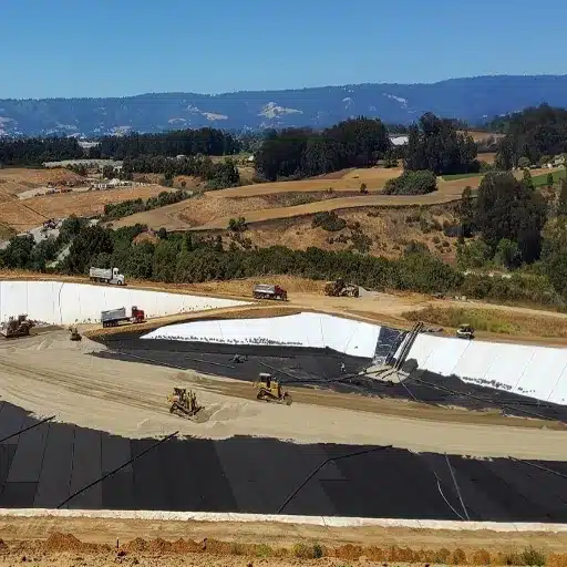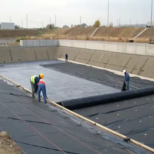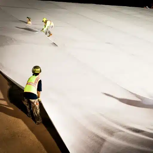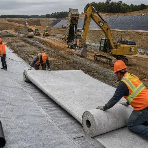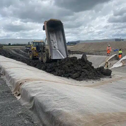
Geomembrane welding is the process of thermally fusing overlapping geomembrane panels–typically HDPE, LLDPE, or PVC–into a continuous, impermeable barrier. Hot-wedge welding dominates production seams on HDPE and LLDPE, while extrusion welding handles repairs, penetrations, and detail work. Getting either method wrong means leaks–and leaks mean environmental liability, regulatory fines, and multi-million-dollar remediation.
Last March, a CQA inspector on a landfill liner project in Texas found something alarming. Twenty percent of the field seams on a 1.5 mm HDPE liner failed air-channel pressure testing. The root cause? A welder temperature sensor reading 25 degrees low. The fix cost $32,000 in cut-outs, re-welding, and re-testing–all preventable with a $500 handheld pyrometer calibration that morning.
If you specify, install, or inspect geosynthetic liners, geomembrane welding quality directly determines whether your containment system performs for five years or fifty. It is the single highest-risk step in any liner project. In fact, welding defects account for roughly 41% of all geomembrane failures–more than subgrade damage, material defects, and cover-soil placement combined.
This guide covers the four primary welding methods with parameter ranges by material, a step-by-step seam testing framework, a defect diagnosis table you can reference in the field, and practical QA planning advice for international projects.
Key Takeaways
- Hot-wedge welding is the standard for HDPE and LLDPE production seams, while extrusion welding handles repairs, pipe boots, and penetrations
- Welding defects cause roughly 41% of geomembrane failures; a correctly calibrated welder eliminates most of them
- Every geomembrane welding project needs three testing tiers: visual inspection, non-destructive air-channel or vacuum-box testing, and destructive peel/shear sampling per ASTM D6392
- HDPE welds at 400-450 ℃, LLDPE at 350-420 ℃, and PVC uses hot air at 200-350 ℃–follow the manufacturer’s welding procedure specification, not generic ranges
- Specifying welder qualification, trial weld frequency, and third-party CQA upfront in procurement documents saves far more than it costs
What Is Geomembrane Welding?
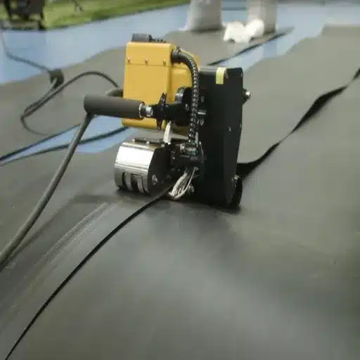
Geomembrane welding fuses overlapping synthetic liner panels through controlled heat and pressure, creating a seam that should approach the strength of the base material itself. A properly executed hot-wedge weld on HDPE can achieve seam strength at roughly 95% of the parent sheet’s tensile strength.
Why this matters: a geomembrane liner is only as continuous as its seams. Even a pinhole measured in millimeters can leak hundreds of liters per day under hydraulic head, and once a liner is buried under cover soil or submerged, finding and fixing that leak costs orders of magnitude more than getting the weld right the first time.
Welding sits inside a broader geomembrane installation workflow–subgrade preparation, panel deployment, welding, testing, anchoring, and cover placement. This article focuses exclusively on the welding phase, with enough technical depth to help engineers, CQA inspectors, and procurement teams specify, execute, and verify seams correctly.
Geomembrane Welding Methods Compared
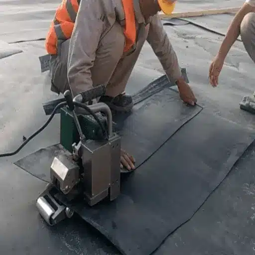
Choosing the wrong welding method for the seam type is a common and costly mistake. Four methods dominate field geomembrane welding.
Hot-Wedge Welding
Hot-wedge welding–also called fusion welding or double-wedge welding–uses a heated metal wedge that slides between two overlapping panels. The wedge melts both surfaces simultaneously, and pressure rollers immediately behind the wedge fuse them.
For HDPE and LLDPE, this is the dominant production method. It creates two parallel weld tracks with a central air channel running between them. That air channel is the key to field testing–you can pressurize it and verify seam continuity without cutting the liner.
Typical hot-wedge equipment is a self-propelled, track-driven machine that runs along the seam at a controlled speed. Wedge temperature, roller pressure, and travel speed are all adjustable. For straight-line production seams on flat grades or gentle slopes, hot-wedge welding is faster, more consistent, and easier to test than any alternative.
Extrusion Welding
Extrusion welding feeds a rod of the same polymer as the base liner through a heated barrel. The molten extrudate flows onto a prepared seam edge and bonds to both panels. The operator controls the extruder by hand, moving it along the seam overlap.
This method is standard for repairs, pipe penetrations, sump details, anchor trench terminations, and that last short seam where a track welder cannot fit. Extrusion welding is slower than hot-wedge and more operator-dependent, but it handles geometry that a track welder cannot reach.
A trial extrusion weld should always be run and destructively tested on site each morning before production welds begin.
Hot Air Welding
Hot air welding directs a stream of heated air onto the overlap surfaces, softening them before the operator applies pressure with a roller. A separate hot-air nozzle and pressure roller give the operator finer control, which is useful on thinner membranes and detail work.
PVC geomembranes are almost exclusively welded with hot air, because PVC degrades at the temperatures a hot wedge generates. Some LLDPE applications with complex slope transitions also use hot air where motorized welders cannot maintain consistent alignment.
Solvent Welding
Solvent or adhesive welding applies a chemical bonding agent to the overlap area. The solvent partially dissolves the PVC surface, and when panels are pressed together, a cold-chemical bond forms.
This method is limited to PVC geomembranes, mostly in tank lining and smaller pond applications where hot air equipment logistics are impractical. It requires careful ventilation, compatible solvent chemistry, and longer cure times. Solvent welds generally do not achieve the peel and shear values of thermal welds.
Welding Methods Comparison Table
| Method | Materials | Best For | Typical Speed | Testing Approach |
|---|---|---|---|---|
| Hot-wedge | HDPE, LLDPE | Straight production seams | 2-5 m/min | Air-channel pressure test |
| Extrusion | HDPE, LLDPE, PVC | Repairs, details, penetrations | 0.5-1.5 m/min | Vacuum box/spark test |
| Hot air | PVC, thin LLDPE | Detail work, short seams | 1-3 m/min | Vacuum box/spark test |
| Solvent | PVC only | Tank linings, small ponds | Manual speed | Visual + spark test |
Welding Parameters and Equipment Setup
Getting the parameters right is what separates reliable geomembrane welding from expensive rework. Every variable–temperature, speed, pressure, and overlap–interacts with material type, liner thickness, and ambient conditions.
Temperature Ranges by Material
Welding temperature is material-specific in geomembrane welding. The polyethylene family (HDPE, LLDPE) needs the highest heat. PVC requires much lower temperatures and, as noted above, is normally hot-air or solvent welded.
| Material | Welding Method | Approx. Temperature Range |
|---|---|---|
| HDPE | Hot-wedge | 400-450 ℃ (750-840 ℉) |
| LLDPE | Hot-wedge | 350-420 ℃ (660-790 ℉) |
| PVC | Hot air | 200-350 ℃ (390-660 ℉) |
These ranges are approximate. Ambient temperature, wind speed, liner thickness, and surface moisture all shift the optimal setting. Always follow the geomembrane manufacturer’s welding procedure specification.
Welding Speed and Pressure
Track welder travel speed typically ranges from 2 to 5 meters per minute for HDPE. Too fast produces a thin, weak weld. Too slow can burn or distort the liner surface. Nip-roller pressure must be sufficient to fuse the molten surfaces without squeezing out too much material.
Overlap Requirements
Standard minimum overlap for hot-wedge production seams is 100 mm (4 inches). Some specifications, particularly for landfill base liners in North America, require 150 mm. The overlap must be clean, dry, and free of wrinkles at the time of welding.
Welder Types
- Manual welders: Handheld hot-air or extrusion tools for detail work
- Semi-automatic: Track-driven hot-wedge welders with operator guidance
- Automatic: Self-guided track welders for long straight runs on level ground
Calibration and Trial Welds
“Every morning, before the first production seam, run a trial weld on a scrap of the same liner material under identical ambient conditions. Destructively peel-test it. If it fails, adjust parameters and run another trial. Only then start welding the liner you intend to keep.”
That is the advice David, a CQA engineer with 15 years of landfill liner oversight, gives every crew he supervises. He keeps a pyrometer in his truck and checks welder temperature displays against it before any seam is laid.
A pre-shift trial weld creates a record of that day’s starting parameters. If a seam fails testing later, the trial data helps isolate whether the problem was parameter drift, weather change, or operator error.
Crews working with HDPE liners should verify equipment calibration daily. For product specifications and thickness options that influence welding parameter selection, see our HDPE geomembrane specifications and thickness options.
Seam Preparation and Field Conditions
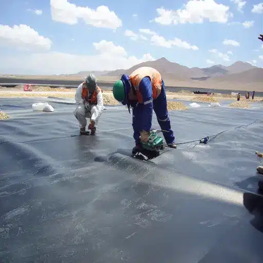
Successful geomembrane welding starts well before the welder touches the liner. Surface preparation, panel alignment, and ambient conditions determine whether a seam bonds correctly the first time.
Surface Cleanliness
Dirt, moisture, oxidation, and oil are the enemies of geomembrane welding. Before welding, the overlap area must be clean and dry. A contaminated seam surface produces a bond that passes visual inspection but fails destructive testing within weeks or months.
Crews should wipe overlap surfaces with a clean, dry cloth. For oxidized or weathered HDPE that has been exposed to UV for more than two weeks, a light surface grind may be needed to expose fresh polymer for welding.
Managing Wrinkles, Expansion, and Stress
Geomembranes expand and contract with temperature. A panel laid in direct sun at 2 p.m. will be measurably longer than the same panel at 7 a.m. If panels are welded under tension or with wrinkles trapped in the seam, thermal cycling eventually opens the weld or tears the adjacent sheet.
Best practice: deploy panels early in the day, allow thermal relaxation, minimize tension, and do not weld over wrinkles. A wrinkle that gets welded in place becomes a permanent stress riser.
Welding in Adverse Conditions
| Condition | Threshold | Action |
|---|---|---|
| Surface moisture | Any visible moisture | Stop; dry overlap area with clean cloths |
| Ambient temp below 0 ℃ | Ice/frost risk | Pre-heat seam area; verify trial weld performance |
| Ambient temp below -5 ℃ | HDPE brittle risk | Suspend welding unless project spec permits |
| Wind above 25 km/h | Cooling and debris risk | Use wind screens; reduce travel speed |
| Rain | Wet surface | Suspend welding until surface is dry |
Pre-Weld Inspection Checklist
- Overlap width correct (100 mm minimum, or per specification)
- Overlap area clean, dry, and free of debris
- No wrinkles crossing the seam path
- Panel alignment acceptable (no fishmouths forming)
- Ambient temperature, humidity, and wind within limits
- Trial weld completed and passed destructive test
Geomembrane Seam Testing: Methods and Acceptance Criteria
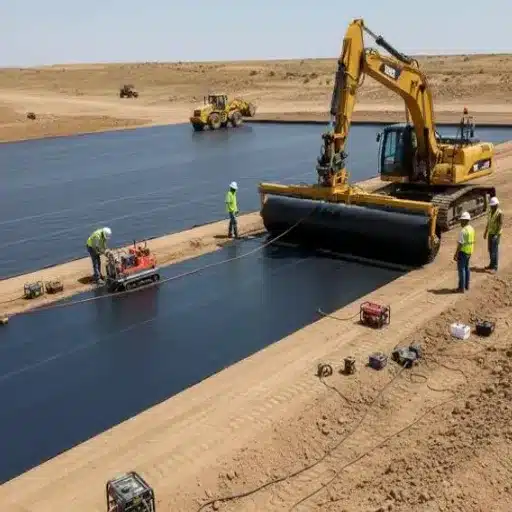
How do you know a geomembrane weld is good? You test it three ways: visually, non-destructively, and destructively. No single method is sufficient, because each geomembrane welding defect type shows up differently under different test conditions.
Non-Destructive Testing
Air-channel pressure test (ASTM D5820)
For double-wedge seams, seal both ends of the air channel between the two weld tracks, pressurize to the specified test pressure (typically 170-205 kPa or 25-30 psi), and hold for a defined period. Pressure loss indicates a leak path through either weld track. This is the fastest and most reliable non-destructive test for production seams.
Vacuum box test
For extrusion welds, single-wedge welds, and repair patches where no air channel exists: place a vacuum box over the seam, apply soap solution, draw a vacuum, and watch for bubbles forming at any leak path. This test is slower but covers seam types that cannot be air-channel tested.
Spark testing
An electrically conductive liner backside and a high-voltage probe detect pinholes invisible to the naked eye. Primarily used on PVC and thin HDPE/LLDPE liners where spark-testable construction is built into the design.
Electrical leak location
After cover placement or water filling, electrode arrays detect current flow through liner defects. This method finds installation damage as well as seam defects, and it is drastically more cost-effective than conventional CQA–$1,186 per problem found versus $7,945 per problem with visual and probe methods.
Destructive Testing (ASTM D6392 / GRI GM19)
Field crews must cut physical seam samples at a frequency defined by the project specification (commonly one sample per 150-200 linear meters of seam). The Geosynthetic Research Institute’s GRI GM19 specification and ASTM D6392 define the standard test methods. The sample is tested for:
- Peel strength: Measures adhesion between sheets (separation force)
- Shear strength: Measures the weld’s ability to resist sliding forces
- Peel separation: Verifies film-tear-bond (failure in parent material, not the weld)
Acceptance criteria vary by material, thickness, and specification, but a passing destructive test generally shows film-tear-bond in peel and shear values approaching the base material’s specified strength. All destructive sample locations must be patched and re-tested using extrusion welding.
Documentation
Every project needs a seam log: date, time, seam number, welder ID, operator name, ambient conditions, welding parameters, non-destructive test results, and destructive sample locations with results. This is auditable quality evidence that protects the owner, the installer, and the engineer.
Common Geomembrane Welding Defects and Prevention
When Martin’s crew welded the 2.0 mm HDPE base liner on a 4-hectare mining tailings facility in Ghana, they kept a defect log on a whiteboard in the site trailer. Systematic defect tracking is the difference between a tight geomembrane welding operation and one bleeding time and material on rework. Every week, the pattern shifted. Week one: cold welds from morning temperature lag. Week two: contamination from dusty winds. Week three: misalignment on the slope transitions. By tracking defects systematically, they cut re-weld rates from 8% to under 2% by week four.
Here is what they tracked and how to prevent each issue:
Defect Diagnosis Table
| Defect | Appearance | Likely Cause | Prevention | Repair |
|---|---|---|---|---|
| Cold weld | Dull surface, no flow lines visible | Temperature too low or speed too fast | Verify pyrometer calibration; reduce speed | Cut out; re-weld |
| Overheating/burn | Discoloration, excessive squeeze-out, thinning | Temperature too high or speed too slow | Reduce temperature; increase travel speed | Cut out; re-weld |
| Contamination in seam | Grit embedded in weld bead, variable bond | Dirty overlap, dusty conditions | Clean overlap with dry cloth immediately before welding | Cut out; clean; re-weld |
| Fishmouth | V-shaped opening at seam edge | Misalignment or tension | Adjust panel alignment; relieve tension before welding | Extrusion weld patch |
| Porosity in extrusion weld | Small bubbles visible on bead surface | Moisture in extrudate or on rod | Keep extrusion rod dry and sealed until use | Grind out; re-extrude |
| Wrinkle in seam | Folded liner visible inside weld track | Panel not relaxed before welding | Deploy early; allow thermal relaxation | Cut out; re-weld |
| Thin squeeze-out | Weld bead narrower than typical | Excessive nip-roller pressure | Reduce roller pressure to manufacturer specification | Cut out; re-weld |
The single most effective prevention measure costs less than $500: a calibrated handheld pyrometer that the CQA inspector uses to spot-check welder wedge temperature against the machine’s display every shift.
Material-Specific Welding Considerations
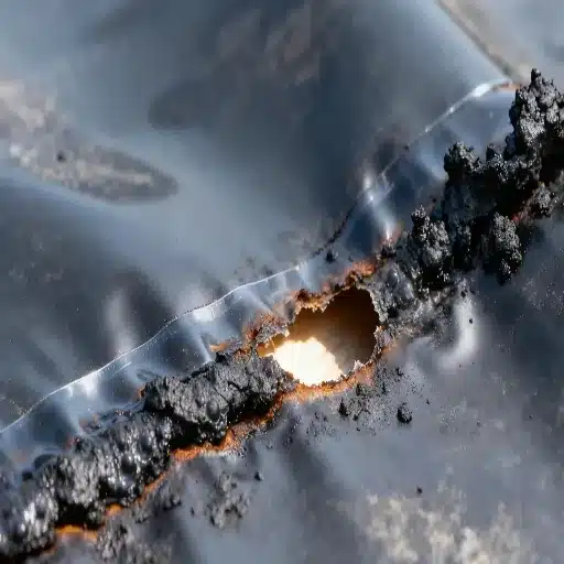
Your choice of liner material–HDPE, LLDPE, or PVC–changes everything about how geomembrane welding should be approached: the method, the parameters, the testing protocol, and the crew skillset required.
HDPE Geomembrane Welding
HDPE is the workhorse of the containment industry. It demands the highest welding temperatures (400-450 ℃) and produces the stiffest seams. Hot-wedge welding is the standard for all straight production seams on HDPE. The material’s high melting point and low thermal conductivity mean weld parameters are sensitive–a 10-degree wedge temperature drop can shift a passable seam to a failed one.
HDPE seams on landfill liner projects typically require 100% air-channel testing of all double-wedge production seams plus destructive sampling every 150 meters. For mining applications like heap leach pads and tailings ponds, chemical resistance and slope stability add complexity to seam design and testing criteria.
LLDPE Geomembrane Welding
LLDPE welds at lower temperatures (350-420 ℃) than HDPE and its greater flexibility makes it more forgiving on irregular subgrades. The same hot-wedge principles apply, but LLDPE’s softer surface requires slightly wider overlap and lower roller pressure to avoid thinning the squeeze-out bead.
The trade-off: LLDPE’s thermal expansion coefficient is higher than HDPE’s, so managing wrinkles and panel relaxation before welding is even more critical. For specification and thickness options, review LLDPE geomembrane options and specs.
PVC Geomembrane Welding
PVC cannot tolerate the temperatures used for polyethylene. Hot air welding at 200-350 ℃ is the field standard. For PVC, solvent welding is the alternative for detail work and tank linings. Spark testing is widely used for PVC seam verification because conductive-backed PVC is commercially available.
PVC welds generally exhibit lower peel and shear values than HDPE or LLDPE welds, but PVC’s lower elastic modulus means seams experience less stress under the same deformation. Selecting between PVC and HDPE for your project involves trade-offs beyond welding; our PVC geomembrane specifications provide additional comparison.
Welder Qualification and QA Planning
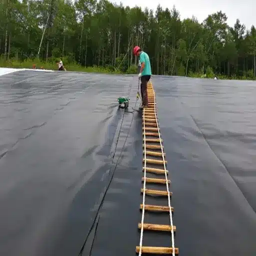
Even the best geomembrane welding equipment produces bad seams in the wrong hands. Welder qualification and a documented QA plan are what turn a crew into a reliable seam production system.
What to Specify in Procurement Documents
Procurement teams and project engineers should define seam quality requirements for geomembrane welding before a welder plugs in a machine. Minimum specification elements:
- Welder operator certification: Require IAGI certification or equivalent documented experience with the specific welding method and material
- Trial weld frequency: Minimum one per shift, per welder, per material/thickness combination
- Non-destructive testing: 100% air-channel test of all double-wedge seams; vacuum box test on all extrusion welds, repairs, and details
- Destructive sampling frequency: Typically one sample per 150-200 linear meters of production seam, or per project specification
- Calibration: Pyrometer check of welder temperature display at shift start and mid-shift
- Documentation: Seam log with welder ID, operator, time, ambient conditions, parameters, and test results
Third-Party CQA vs Installer QC
A project specification should distinguish between installer quality control (QC)–the installer’s own verification–and construction quality assurance (CQA)–independent third-party oversight. Both matter, but CQA provides the owner with verification that someone without a financial interest in weld acceptance rates is documenting the results.
For International Buyers
If you are procuring geomembrane liners from a global supplier like Shanxi Shengxing for a project abroad, three things matter for welding QA:
- Confirm that the liner material is compatible with the welding equipment available at the project site. Different manufacturers’ HDPE formulations can have slightly different welding temperature windows.
- Request a welding procedure specification (WPS) from the liner manufacturer. This should include recommended temperature, speed, pressure, and acceptable ambient condition ranges for that specific material and thickness.
- Ensure sample retention and QA documentation are included in your order. Our products are manufactured under strict quality control with sample retention for traceability.
Need technical guidance on welding parameters for your specific project? Contact our engineering support team for material-specific welding recommendations.
Frequently Asked Questions
How do you weld geomembrane panels together?
Geomembrane panels are welded by overlapping adjacent sheets and applying controlled heat and pressure along the overlap. The two primary methods are hot-wedge welding for straight production seams and extrusion welding for repairs, pipe penetrations, and detail work. Proper geomembrane welding requires clean, dry overlap surfaces, calibrated equipment, and verified trial welds before production seams begin.
What is the best welding method for HDPE geomembrane?
Hot-wedge (double-wedge) welding is the standard for all straight production seams on HDPE. It is faster than extrusion welding, creates an air channel for reliable non-destructive testing, and produces consistent fusion with less operator dependence than manual methods.
How do you test geomembrane seams in the field?
Three tiers: (1) visual inspection of every seam for bead continuity, color, and squeeze-out; (2) 100% non-destructive testing–air-channel pressure test for double-wedge seams and vacuum box for extrusion welds and details; (3) destructive peel and shear testing on samples cut from production seams at specified intervals per ASTM D6392.
What temperature should HDPE geomembrane be welded at?
HDPE hot-wedge welding typically operates between 400 ℃ and 450 ℃ (750-840 ℉). Actual optimal temperature depends on material thickness, ambient conditions, and the specific manufacturer’s formulation. Always follow the manufacturer’s WPS and verify with daily trial welds.
Can geomembrane be welded in cold weather?
Yes, with caveats. At ambient temperatures below 0 ℃, pre-heat the seam overlap area and verify trial weld performance before production welding. Below -5 ℃, most specifications require suspension of welding unless the project documents explicitly permit it and trial weld results are acceptable.
How often should geomembrane seams be tested destructively?
Typical specifications require one destructive sample per 150-200 linear meters of production seam. More frequent sampling may be specified for critical applications like landfill primary liners or single-lined hazardous containment.
What causes geomembrane weld failures?
The most common causes are incorrect welding temperature (too low = cold weld; too high = burn), contaminated seam surfaces, welding over wrinkles or moisture, insufficient overlap, and operator error on manual extrusion welds. Regular pyrometer calibration and daily trial welds prevent most of these failures.
Conclusion
Geomembrane welding is where liner specifications meet field reality. A roll of HDPE or LLDPE arrives on site as discrete panels; only welding makes it a continuous barrier. That transformation depends on three things: the right method for the seam type, properly set and verified parameters, and systematic testing at every stage.
The data is clear: welding defects drive roughly 41% of liner failures. The cost of poor welding–$32,000 in the Texas landfill case, 12 million euros in the Chile heap leach replacement–dwarfs the cost of daily pyrometer checks, trial welds, and proper testing. Every dollar spent on welding QA returns multiples in avoided remediation.
If you are specifying geomembrane materials for an upcoming project, getting the welding right starts with the liner itself. Our HDPE, LLDPE, and PVC geomembranes ship with manufacturer-recommended welding parameters to give your field crew a verified starting point. We also provide technical consultation to help procurement teams define seam quality requirements before a single panel arrives on site.