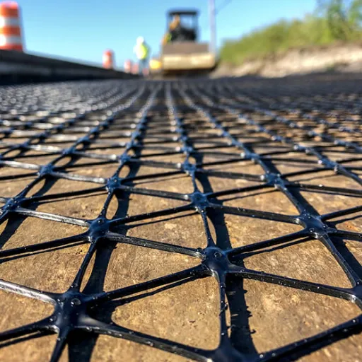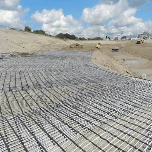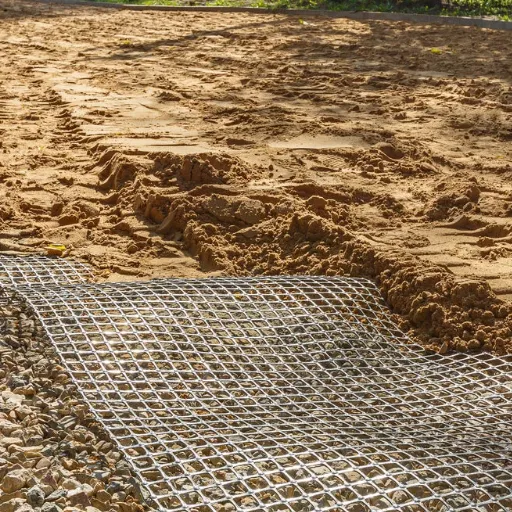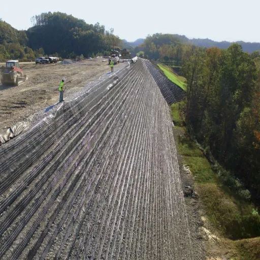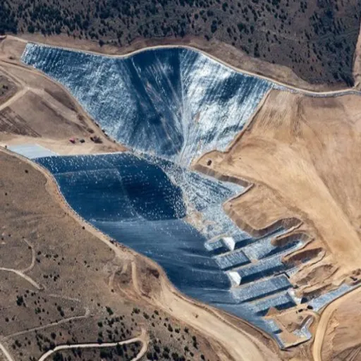
Geogrid creep is the slow, permanent elongation of a geogrid under a sustained load. It governs long-term design because the strength you can actually use for 75 or 120 years is often only one-third to one-half of the ultimate tensile strength printed on the datasheet.
In 2024, Aisha Rahman, a design engineer in Jakarta, specified a geogrid with 200 kN/m ultimate strength for a 9 m highway retaining wall. The number looked generous.
Then she applied the manufacturer’s creep reduction factor of 2.8, plus installation damage and durability factors. The long-term design strength dropped to about 62 kN/m. Her reinforcement spacing changed from 0.6 m to 0.4 m, and the geogrid quantity rose by roughly 38%.
The wall stayed safe. The budget did not stay unchanged. Creep had been treated as a footnote, and it turned out to be the main cost driver.
If you have ever compared two geogrid datasheets and wondered why a 200 kN/m product gets specified where a 400 kN/m product is also sold, you already understand the problem. Ultimate strength is the headline. Creep is the fine print that decides whether the headline means anything.
This guide explains what geogrid creep is, how labs measure it, how 10,000-hour tests become 120-year predictions, and how to check a supplier’s creep reduction factor before it reaches your design. You will also see where standard test methods disagree, why confinement and temperature change the answer, and which details to demand in a test report.
Key Takeaways
- Geogrid creep is time-dependent strain under sustained load, and it often controls the long-term design strength (LTDS) of reinforced soil structures.
- LTDS equals ultimate tensile strength divided by the product of reduction factors; the creep reduction factor (RF_CR) is frequently the largest of them.
- Standard creep tests run for 10,000 hours, about 1.14 years, and time-temperature superposition or SIM extrapolates the data to 10^6 hours, roughly 120 years.
- Polymer type drives the factor: PET geogrids typically use RF_CR of 1.6 to 2.5, HDPE 2.6 to 5.0, and PP 4.0 to 5.0.
- A credible report states the strain limit, test temperature, confinement condition, extrapolation method, and lot-specific ultimate strength, not just a single reduction number.
What Is Geogrid Creep?
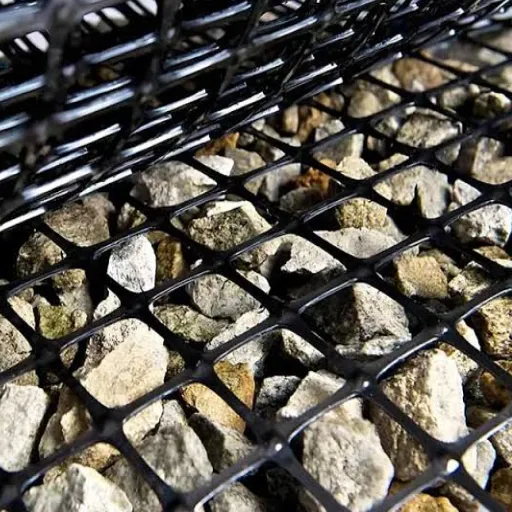
Creep is deformation that continues after the load stops increasing. Put a constant tensile load on a polymer geogrid and it stretches immediately, then keeps stretching slowly.
The first stage, primary creep, decelerates. The second stage, secondary creep, proceeds at a nearly steady rate. The third stage, tertiary creep, accelerates until rupture.
Good design keeps a geogrid in secondary creep for its entire service life. If the sustained load is high enough to push the material into tertiary creep, failure is only a matter of time.
Geogrids are viscoelastic. Their response depends on load, time, and temperature at the same time. A rib that feels stiff in your hand at 20°C can behave differently at 40°C under a constant 40% of its ultimate load for decades. That’s why a single short-term tensile test can’t answer a long-term design question.
Two locations matter. The first is the rib itself, where the polymer molecules gradually align and slide. The second is the junction, where longitudinal and transverse ribs meet.
Junction creep can allow the grid to open up under load, especially in some welded or bonded products. A creep program that tests only rib strips may miss the weakest point.
Geogrid creep also depends on confinement. A grid buried in compacted aggregate is held by interlock and friction, which restricts movement. An unconfined strip in a laboratory sees none of that restraint. The lab test is therefore conservative, but the gap between lab and field is not unlimited.
If you are still mapping the broader product landscape, our geogrid stabilization guide covers the main types, functions, and applications before you narrow down to creep behavior.
Comparing creep factors across suppliers? Our engineering team can review the datasheets with you and flag inconsistent assumptions. Talk to our geogrid team.
Why Creep Governs Long-Term Design Strength
Long-term design strength is the load a geogrid can carry for the design life without exceeding the allowable strain or rupturing. The usual framework is:
LTDS = T_ult / (RF_CR × RF_ID × RF_D)
Where:
- T_ult is the ultimate tensile strength, ideally from the specific lot or production period.
- RF_CR is the creep reduction factor.
- RF_ID is the installation damage reduction factor.
- RF_D is the durability reduction factor for chemical and environmental exposure.
Geogrid creep is often the source of the largest factor. For a PET geogrid with RF_CR of 2.2, installation damage of 1.1, and durability of 1.05, the denominator is 2.54. A 200 kN/m product becomes 78.7 kN/m. The designer then applies a further factor of safety, and the usable load falls again.
This is why comparing geogrids by ultimate strength alone is misleading. Two products with the same 200 kN/m label can have very different design strengths if one uses a creep factor of 1.8 and the other uses 3.2.
The reduction factors interact with the structure type. In a retaining wall, the reinforcement must hold the design load at a strain limit that keeps the facing movement acceptable. In a roadway base, the grid works in confinement and the relevant strain limit may be different. The same product can therefore have more than one valid creep factor, depending on the application and the assumed confinement.
For the load side of the calculation, including how reinforcement tension is derived from soil pressure and surcharge, see our guide to geogrid soil reinforcement. For the full limit-state framework and factor combinations, reinforced soil design walks through the wider design sequence.
A simple way to sanity-check a quote is to divide the ultimate strength by the creep factor before you compare prices. If a supplier can’t state the strain limit and design life behind its factor, the number isn’t comparable.
Creep Rupture vs Creep Strain
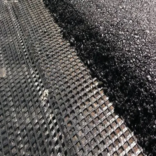
There are two different failures to worry about, and they get confused constantly.
Creep rupture means the geogrid breaks after carrying a sustained load for some period. The test asks: at what constant load does this product survive 1, 10, or 100 years?
Creep strain means the geogrid deforms too much, even if it never breaks. The test asks: what load produces 5% or 10% strain at the design life?
Most reinforced soil design is governed by strain, not rupture. A wall can remain physically intact while the reinforcement elongates enough to crack the facing, pull the connections, or redistribute load in ways the design did not anticipate. A roadway can remain unbroken while differential movement damages the pavement.
This distinction explains why creep-limited strength is usually lower than rupture strength. A product might survive 45% of its ultimate load for 100 years, but reach 10% strain at only 30% of ultimate. If your design limit is 10% strain, the second number controls.
Isochronous curves make the relationship visible. Each curve shows stress versus strain at a fixed time, for example 1 hour, 1,000 hours, and 100,000 hours. As time increases, the curve shifts downward and to the right. The creep-limited strength at your chosen strain and design life is read from the relevant curve.
This is also why a test report that only gives a rupture load is incomplete for most design work. You need the strain associated with that load, and the time associated with that strain.
How Geogrid Creep Is Tested (ASTM D5262 and ISO 13431)
The core geogrid creep methods are ASTM D5262 and ISO 13431. Both apply a constant tensile load to a specimen and record extension over time. The specimen is usually a wide strip containing several ribs and at least one junction, not a single isolated rib.
Test loads are commonly spaced between about 20% and 60% of ultimate tensile strength. Lower loads produce slow creep. Higher loads risk rupture before the test ends. A typical program uses three or more load levels so the lab can construct a family of curves rather than a single point.
The standard duration is 10,000 hours, which is about 1.14 years. Some specifications require 1,000-hour screening tests first, then extend the survivors. Temperature is normally held at 20°C, with additional temperatures used for accelerated extrapolation.
Several related methods show up in specifications:
- ASTM D6992 covers the stepped isothermal method (SIM), which raises temperature in steps on a single specimen to accelerate creep.
- ISO/TS 20432:2022 provides guidance on extrapolating geosynthetic creep data.
- AASHTO R69 and WSDOT T925 are used in some North American transport specifications.
- GRI-GG4 is the Geosynthetic Institute’s protocol for geogrid creep testing and reduction factor derivation.
- ASTM D6637 and EN ISO 10319 cover wide-width tensile strength, the short-term test that anchors the creep load levels.
Confined creep testing adds a soil or aggregate confinement cell. The FHWA/GeoSyntec confined creep protocol is one widely cited approach. Confinement better represents a buried grid, but it also adds variability, so unconfined tests remain the common baseline.
The Geosynthetic Institute publishes the GRI protocols, while ASTM International and the International Organization for Standardization maintain the core test standards. Always confirm which edition a report used, because methods and acceptance criteria change.
From 10,000 Hours to 120 Years
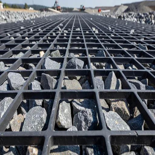
No one runs a 120-year test. The industry extrapolates.
The standard approach for geogrid creep data is time-temperature superposition (TTS). Creep tests are run at several temperatures, usually 20°C, 30°C, 40°C, and sometimes 50°C. Higher temperatures make the polymer creep faster, so a test at 40°C can represent a much longer period at 20°C. The lab shifts each curve horizontally using an Arrhenius-type factor until the curves overlap into one master curve.
From the master curve, the lab generates isochronous curves at the target design life and reads the creep-limited strength at the specified strain. A common target is 10^6 hours, which is about 114 years, often rounded to 120 years.
The extrapolation is only as good as its assumptions. Three things matter most:
- The shift factor model. Arrhenius assumes a single activation energy. Real polymers can change mechanism at high temperature, so the highest test temperature may not belong on the same master curve.
- The test duration. Extrapolating from 1,000 hours to 10^6 hours is a factor of 1,000. Extrapolating from 10,000 hours is a factor of 100. The shorter the test, the more the answer depends on the model.
- The failure mode. A 2026 study on HDPE geogrids found that SIM-based predictions diverged from conventional creep data beyond about 1,000 hours, and that reduction factors depended heavily on whether the criterion was rupture or 20% strain. The study reported RF_CR values of 3.04 and 2.43 at 20% strain for different extrapolation approaches, against 2.30 for rupture. In other words, the same product can produce different factors depending on the method and the limit state.
That doesn’t make extrapolation invalid. It makes documentation essential. A report should state the temperatures used, the shift model, the measured durations, the target life, and the strain criterion. A single RF_CR without that context is a number without a basis.
Creep Reduction Factors by Polymer
Geogrid creep behavior varies with polymer chemistry, and the chemistry sets the practical range. The following values are typical for geogrid design, based on published creep studies and manufacturer data. They are ranges, not universal constants.
| Polymer | Typical RF_CR | Typical 120-year strength retention | Notes |
|---|---|---|---|
| PET (polyester) | 1.6 to 2.5 | About 50% | Good creep resistance, sensitive to hydrolysis in some environments |
| HDPE | 2.6 to 5.0 | About 39% | Higher modulus, but more creep under sustained load |
| PP (polypropylene) | 4.0 to 5.0 | Lower than PET | Creeps roughly 10 times more than PET at 20°C in some comparisons |
| Aramid | Lower than PET | About 65% | High strength retention, higher material cost |
The classic reference values from Lothspeich and Thornton illustrate the spread: PET at 1.61 to 1.62, HDPE at 2.69 to 3.04, and PP at 3.27 to 4.63. The exact value depends on the product, the strain limit, and the extrapolation.
The 120-year retention figures deserve context. One comparative study reported 39.1% for HDPE, 51.5% for PET, and 65.4% for aramid. Those numbers describe how much of the initial load the material can sustain after 120 years at the test conditions. They are not the same as the RF_CR, because the factor also depends on the reference ultimate strength and the chosen strain limit.
Temperature sensitivity is not uniform. For polyethylene, a change from 10°C to 20°C can shift the time scale by roughly a factor of 10. A product tested only at 20°C may look better than it behaves in a hot climate, and a product tested in a cool laboratory may look worse than it behaves in service.
Manufacturer data shows how much the factor varies by product family. Published values include Miragrid at about 1.45 with 72% retention at 120 years, ACEGrid at about 1.41 with 71%, Tensar UX1700HS at about 2.60, and TerraGrid HSG at 1.36 to 1.45 depending on design life. These are product-specific claims, not generic polymer properties, and they should be verified against the current test report.
Now consider Daniel, a procurement lead in Nairobi. He received two quotes for a 40 kN/m design requirement. Supplier A offered a 180 kN/m geogrid at $2.10/m² with RF_CR of 4.0. Supplier B offered a 160 kN/m geogrid at $2.30/m² with RF_CR of 2.5.
On ultimate strength, A looked stronger. After the creep factor, A delivered 45 kN/m and B delivered 64 kN/m before other reductions. B cost 9.5% more per square meter but delivered 42% more design strength. Daniel bought B.
The lesson is not that one polymer always wins. It is that the creep factor belongs in the commercial comparison, not only in the design check.
For the durability side of the same question, including hydrolysis, UV exposure, and antioxidant depletion, see our article on geogrid service life.
Confined Creep, Temperature, and Real-World Conditions
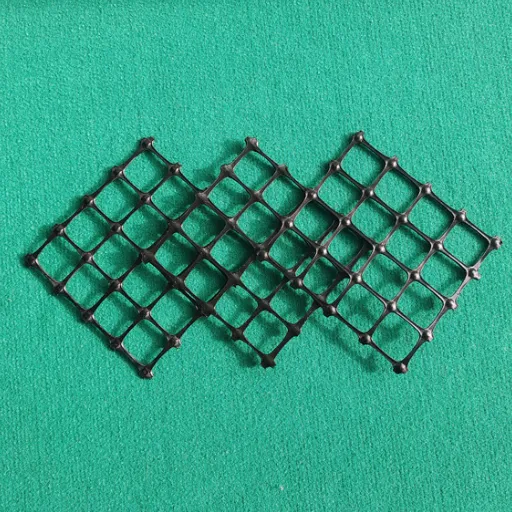
Laboratory geogrid creep tests are usually unconfined. Field geogrids are confined by soil, aggregate, or concrete facing. Confinement changes the answer.
One study found that confinement at 138 kPa improved the 5% modulus of geogrids by roughly 5% to 30%, depending on the product and the soil. The improvement is real but modest. It doesn’t justify ignoring creep, and it doesn’t turn a high-creep product into a low-creep product.
Temperature is the larger field variable in many projects. Black geogrids in direct sun can reach temperatures well above ambient before backfill covers them. Once buried, temperature swings are smaller but not zero, especially near the surface or in shallow embankments. A design that uses a 20°C factor in a 40°C service environment should justify the choice.
Installation damage matters too. A grid dragged over sharp aggregate loses strength before it ever carries load. That loss is handled by RF_ID, but severe damage can also change the creep response by creating stress concentrations at nicks and cuts. Good specification and inspection reduce this risk more than any factor can.
Field evidence is encouraging but should be read carefully. A 25-year-old geogrid-reinforced wall in Norway showed measured strains of only 0.2% to 0.8%, far below the 10% strain often used in certification. The result supports the conservative nature of unconfined lab testing and the benefit of good compaction and confinement. It doesn’t prove that every product will behave the same way, because the wall used a specific product, soil, and load history.
Design codes reflect the uncertainty. BS 8006-1 uses strain limits around 0.5% and 1.0% for different reinforcement conditions, while French guidance has allowed limits in the 3% to 6% range depending on the structure. A higher strain limit allows a higher creep-limited strength, but it also allows more movement. The right limit depends on what the structure can tolerate, not on what makes the datasheet look best.
How to Read a Geogrid Creep Test Report
A geogrid creep test report is not a pass-or-fail certificate. A creeping geogrid is not a defective product. It is a viscoelastic material behaving as expected.
The question is whether the reported factor matches your design conditions. Use this checklist before accepting a supplier’s RF_CR.
1. Identify the test standard and edition. ASTM D5262, ISO 13431, GRI-GG4, and SIM methods are not interchangeable. The edition matters because acceptance criteria and extrapolation guidance change.
2. Check the specimen. Confirm that the test used a wide specimen with junctions, not a single rib. Junction creep can control performance in some products.
3. Check the load levels. Loads should span a useful range, typically about 20% to 60% of ultimate strength. A report with only one high load level may be a rupture test, not a creep design test.
4. Check the temperature and duration. A 1,000-hour test at a single temperature is a screening test. A 10,000-hour test at multiple temperatures supports extrapolation. Know which one you are looking at.
5. Check the strain limit and design life. RF_CR is meaningless without the strain criterion and the target life. A factor derived at 10% strain for 75 years is not the same as one derived at 5% strain for 120 years.
6. Check the extrapolation. Look for the shift model, the highest temperature used, and whether the master curve was validated against measured long-term data. Be cautious when a 1,000-hour SIM result is presented as a 120-year certainty.
7. Check the ultimate strength basis. The factor should be tied to a lot-specific or statistically supported ultimate strength, not a nominal brochure value. If the report uses a different T_ult than the datasheet, the design strength changes.
8. Check confinement and application. An unconfined factor is conservative for buried reinforcement. If the supplier claims a confined factor, ask for the confinement stress and test setup.
Our guide to geogrid specifications explains how tensile strength, junction efficiency, and aperture size fit into the same specification package. A creep report is one part of the evidence, not the whole file.
When Mei Lin, a design reviewer in Singapore, audited a 120-year extrapolation for a coastal project, the report looked impressive until she checked the temperature column. All tests had run at 20°C, and the extrapolation assumed a single Arrhenius factor to 10^6 hours.
The product was probably fine. The evidence was thinner than the headline suggested. She requested a multi-temperature dataset and a lower strain limit for the connection design. The supplier complied, and the project avoided an assumption that would have been hard to defend in a peer review.
Need the creep test documentation behind a quote? We can supply product-specific reports and help you compare factors on the same basis. Request test documentation.
FAQ
How much does geogrid creep reduce design strength?
Geogrid creep reduces design strength by a substantial margin, depending on the polymer and the strain limit. PET geogrids commonly use RF_CR of 1.6 to 2.5, HDPE 2.6 to 5.0, and PP 4.0 to 5.0. After installation damage and durability factors, the usable long-term strength is often one-third to one-half of ultimate tensile strength.
What is the difference between creep rupture and creep strain?
Creep rupture is breaking under a sustained load. Creep strain is deforming too much without breaking. Most reinforced soil design is governed by strain because excessive elongation can damage the facing, connections, or pavement even if the grid remains intact.
How long does a geogrid creep test take?
The standard test duration is 10,000 hours, about 1.14 years. Many programs run 1,000-hour screening tests first, then extend selected specimens. Accelerated methods such as SIM can produce data faster, but they still require validation against conventional creep results.
Can 10,000-hour data really predict 120 years?
It can provide a defensible estimate when the test uses multiple temperatures, a validated shift model, and a clear strain criterion. The extrapolation is a prediction, not a measurement. Treat it as one line of evidence and check it against field performance and the supplier’s quality control data.
Does soil confinement reduce geogrid creep?
Yes, but the effect is moderate. Confinement at 138 kPa has improved the 5% modulus by roughly 5% to 30% in published studies. It helps, but it does not eliminate creep, and unconfined lab factors remain a conservative baseline for design.
Which geogrid polymer has the lowest creep?
Aramid generally shows the highest strength retention, followed by PET, then HDPE, then PP. The lowest creep factor is not automatically the best choice, because cost, durability, installation damage, and availability also matter. Compare design strength per unit cost, not ultimate strength per unit cost.
Conclusion
Geogrid creep is the quiet force behind every long-term reinforcement decision. It determines how much of the ultimate strength you can actually use, and it often matters more than the number on the front of the datasheet.
The practical rules are simple. Start with the design life and strain limit. Get the product-specific creep reduction factor.
Confirm the test standard, temperature, duration, and extrapolation method. Apply the factor alongside installation damage and durability, then compare suppliers on design strength rather than ultimate strength.
Do that, and a 200 kN/m geogrid will not surprise you with a 62 kN/m design strength after the quote is signed. You will know the number before you commit.
If you want a geogrid recommendation built around your design life, strain limit, and soil conditions, our team can match the product and documentation to the application. Request a geogrid quote or send your project details for a technical review.