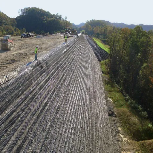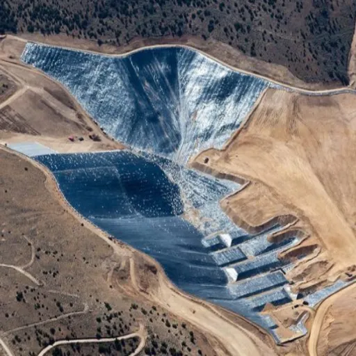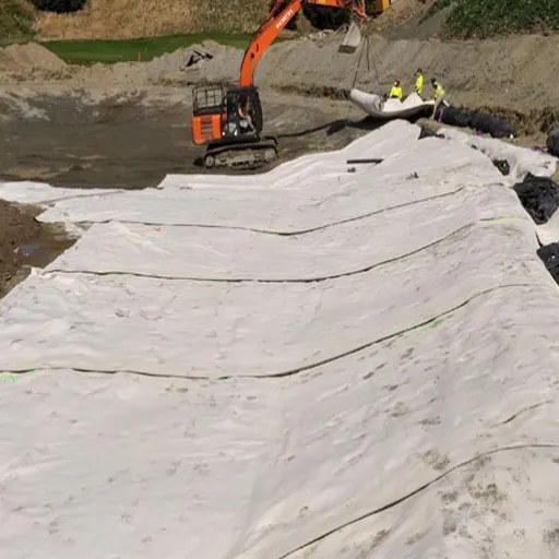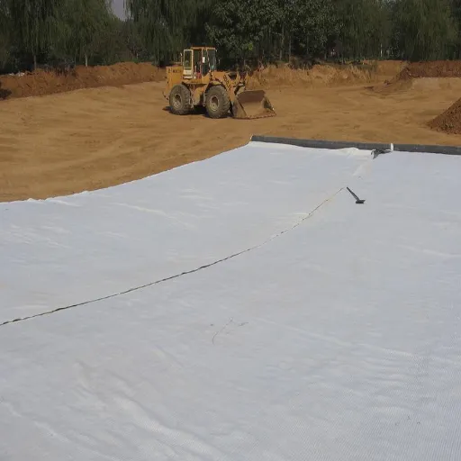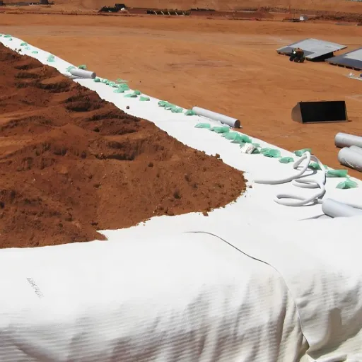
Reinforced soil design is the engineering process of proportioning a composite structure, compacted soil fill plus horizontal layers of tensile reinforcement and a facing, so that the soil-reinforcement mass resists internal rupture and pullout as well as external sliding, bearing, and global failure with an adequate factor of safety. It is a discipline, not a product. The same method designs a 2 m garden wall, a 12 m highway MSE wall, a steep reinforced slope, and a bridge abutment. The difference lies in the geometry, the loads, and the code you design to.
The stakes are easy to underestimate. In 2019, a municipal team in the Pacific Northwest approved a 5.5 m (18 ft) reinforced soil wall using rule-of-thumb reinforcement lengths borrowed from a manufacturer brochure. Two winters later the wall had rotated 40 mm at the crest and cracked three facing panels. A redesign found the reinforcement ended just short of the governing failure surface, and the soil had been built wet with no drainage. The fix cost more than the original wall. Every one of those failures was a design failure, not a material failure.
That pattern is why reinforced soil design matters more than material choice. This guide explains what reinforced soil design is, the structure types, the codes that govern it, the step-by-step design process, the internal and external stability checks, the factors of safety, the spacing and length rules, the software engineers use, and the mistakes that sink walls and slopes. Whether you are a geotechnical engineer, a contractor, or a procurement buyer, you will finish able to read a design, question a supplier, and specify with confidence.
Key Takeaways
- Reinforced soil design is the process that makes compacted soil and tensile reinforcement behave as one composite gravity mass; the reinforcement supplies the tensile strength soil lacks.
- Every structure must satisfy two groups of checks: internal stability (rupture and pullout) and external stability (sliding, bearing, eccentricity, and global or compound failure).
- Match the safety framework to the governing code: FHWA ASD uses factors of safety (sliding >= 1.5, bearing >= 2.0, global >= 1.5), while AASHTO LRFD and BS 8006-1 express the same safety as resistance or partial factors.
- Long-term design strength is the number that governs: T_al = T_ult / (RF_ID x RF_D x RF_CR), typically 33 to 50 percent of the ultimate tensile strength.
- Geosynthetic-reinforced walls commonly cost 30 to 60 percent less than concrete walls and can cut embodied carbon by up to 98 percent, with the advantage narrowing at greater wall heights.
What Is Reinforced Soil Design?
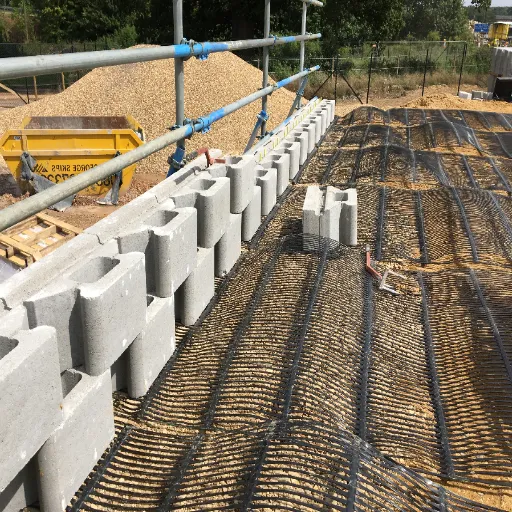
Reinforced soil design is the engineering method that combines compacted soil fill, horizontal planar reinforcement, and a facing into a single structural mass, then verifies that the mass is stable against internal and external failure with an adequate factor of safety.
The founding principle is simple. Soil is strong in compression and weak in tension. A slope stands because it is pushed together, but it fails when it is pulled apart along a slip surface. Reinforcement, whether a polymer geogrid, a woven geotextile, or a steel strip, adds the tensile strength the soil lacks. When the reinforcement is laid horizontally and interlocked with the soil, the two materials act together as a composite that is far stronger and stiffer than the soil alone.
The concept is not new. Henri Vidal, a French engineer, patented the Reinforced Earth system in the early 1960s using steel strips. His insight, that friction between soil and reinforcement transfers stress into the reinforcement, still underpins every modern reinforced earth design method. Today “reinforced soil” and “mechanically stabilized earth” (MSE) are generic terms, applied to structures from 1 m garden walls to 30 m highway abutments.
If you want the deeper physics of how reinforcement actually carries load, the mechanisms of geogrid soil reinforcement explain interlock, lateral restraint, and tensioned membrane action in detail. This guide stays at the design level: how you turn those mechanisms into a safe, buildable, code-compliant structure.
Types of Reinforced Soil Structures
Reinforced soil design looks different depending on what you are building. The four families below cover almost every project, and each drives a different analysis approach and a different facing system. Knowing which family you are in sets the terms for MSE wall design, reinforced soil slope design, or foundation reinforcement.
| Structure type | Angle or threshold | Analysis approach | Typical facing |
|---|---|---|---|
| Reinforced soil wall (MSE/GRS) | Near-vertical (batter <= 20 degrees) | Lateral earth-pressure method | Segmental block, precast panel, wrapped face |
| Reinforced soil slope (RSS) | Batter greater than 20 degrees | Limit-equilibrium slope stability | Wrapped geogrid, vegetated, or none |
| Reinforced embankment / foundation | Basal, under fill | Sliding, bearing, and settlement checks | Not applicable (basal reinforcement) |
| Bridge abutment / wing wall | Support structure | Combined wall and bearing checks | Panels, blocks, or wire facing |
Reinforced Soil Walls (MSE and GRS)
A reinforced soil wall is the most common expression of reinforced soil design. The face is near-vertical, and the structure is analyzed with lateral earth-pressure theory. The critical distinction inside this family is MSE versus GRS.
In a conventional MSE wall, the reinforcement is connected to the facing, typically segmental concrete blocks or precast panels, and the connection is a design element in its own right. In a geosynthetic reinforced soil (GRS) wall, the reinforcement is spaced very closely, no more than about 300 mm (12 in), and the facing does not need a structural connection because the closely spaced layers confine the soil so tightly that the face is only a retainer. GRS is the basis of the FHWA’s integrated bridge system, which supports bridge loads directly on the reinforced fill.
Reinforced Soil Slopes (RSS)
When the face is battered rather than vertical, the structure is a reinforced soil slope. Here reinforced soil slope design takes over, using a limit-equilibrium stability analysis that checks circular and wedge failure surfaces through and behind the reinforced zone. A reinforced slope can be built much steeper than an unreinforced one. A natural slope is generally limited to about 2H:1V, while a reinforced slope can reach 1.5H:1V, 1H:1V, and steeper with a wrapped or vegetated face. This is common on highway cuts and residential developments where right-of-way is tight.
Reinforced Embankments and Foundations
The same principles support embankments on soft ground. Basal reinforcement laid across the full width transfers the embankment weight outward, improving stability and controlling settlement over soft clay or peat. Here the design focus is sliding, bearing, and global stability rather than wall geometry.
For the application-level detail behind these types, our geogrid retaining wall design guide covers MSE walls, and the geogrid slope stabilization overview covers slopes and embankments.
Reinforced Soil Design Codes & Standards
Reinforced soil design is governed by published codes, and matching the right code to the project jurisdiction is the first decision in any reinforced soil structure design. The table below maps the main frameworks.
| Code or standard | Region | Method | Structures covered |
|---|---|---|---|
| FHWA-NHI-10-024 / -025 (GEC 011) | US | ASD and LRFD | MSE walls and reinforced soil slopes |
| AASHTO LRFD Bridge Design Specifications | US | LRFD | Highway structures, abutments |
| NCMA SRW Design Manual | US | ASD / LRFD | Segmental block retaining walls |
| BS 8006-1:2010+A1:2016 | UK / International | Limit state (partial factors) | Walls, slopes, foundations; steel and polymer reinforcement |
| FHWA-HRT-11-026 / -027, HRT-17-080 | US | LRFD (GRS) | GRS abutments and integrated bridge systems |
| AS 4678:2002 | Australia | Limit state | Earth-retaining structures |
| IRC SP 49:2014 | India | Working stress / limit | Geosynthetics in highway engineering |
FHWA and AASHTO (United States)
The FHWA Geotechnical Engineering Circular No. 11, published as FHWA-NHI-10-024 and -025, is the reference work for MSE walls and reinforced soil slopes in the United States. It presents both allowable stress design and load and resistance factor design, and it includes seismic provisions. AASHTO LRFD governs highway structures and abutments, and the NCMA manual covers segmental retaining walls.
BS 8006-1 (UK and International)
BS 8006-1:2010+A1:2016 is a limit-state code of practice covering strengthened and reinforced soils, with partial factors applied to loads, soil properties, and soil-reinforcement interaction. It requires external, internal, and compound stability to be checked. Note that Eurocode 7 does not itself cover reinforced soil; the UK National Annex points designers back to BS 8006-1, so a project expecting “Eurocode compliance” still needs this code.
The lesson from the Pacific Northwest wall applies here. The design team used the right materials but the wrong method and skipped the governing code’s failure-surface requirement. Reinforced soil design begins with selecting the standard and following it exactly.
The Reinforced Soil Design Process: Step by Step

Every reinforced soil design, whether a two-layer garden wall or a 20 m abutment, follows the same logical sequence. The steps are iterative; you adjust the reinforcement layout until the target factor of safety is achieved.
- Establish geometry and loading. Define the structure height, face batter, crest slope, surcharge, traffic loading, seismic demand, and groundwater conditions. These fix the driving forces.
- Determine soil properties. Characterize the in-situ, foundation, reinforced fill, and retained fill soils. You need the friction angle, or cohesion for fine soils, and the unit weight for each.
- Select the reinforcement. Choose the type and polymer based on the structure and durability demands, then set the strength class and the reduction factors.
- Check the unreinforced case. Analyze the unreinforced slope or wall to confirm reinforcement is needed and to locate the critical failure surface.
- Design for internal stability. Compute the maximum tensile force in each reinforcement layer and verify it against both rupture and pullout.
- Check external stability. Verify sliding, bearing capacity, eccentricity, and global or compound stability for the reinforced mass as a rigid body.
- Verify serviceability, drainage, and durability. Estimate deformations, design the drainage system, and confirm the reinforcement meets the design life.
Steps 4 through 7 are where most reinforced soil design failures originate. Skipping the unreinforced check means you never find the critical surface. Skipping drainage means you design for dry soil that will not exist. Skipping durability means a strong wall that rots or creeps.
If your project sits at the edge of these decisions, our engineering team can review the approach and recommend a reinforcement specification for your geometry. Contact engineering support before the design is frozen, not after.
Internal Stability: Rupture & Pullout Design
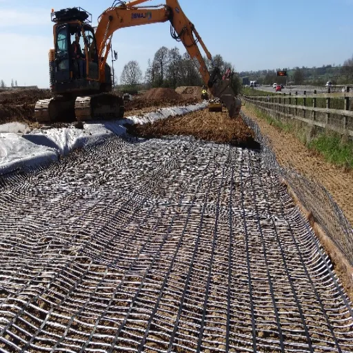
Internal stability asks a single question: will the reinforcement itself survive the load? There are two failure modes to prevent. Rupture, where the reinforcement breaks, and pullout, where the reinforcement slides out of the soil because friction is insufficient.
Rupture: The Reinforcement Must Not Break
For each layer, you compute the maximum tensile force, T_max, from the lateral earth pressure acting on the tributary area of that layer. That force must not exceed the reinforcement’s allowable long-term design strength.
The design strength is where reinforced soil design gets serious. You start with the ultimate tensile strength, T_ult, measured per ASTM D6637 for geogrids, and reduce it with three factors:
T_al = T_ult / (RF_ID x RF_D x RF_CR)
- RF_ID (installation damage): 1.1 to 2.0, reflecting the damage the reinforcement suffers during placement and compaction.
- RF_D (durability): 1.0 to 1.5, covering chemical and biological degradation over the design life.
- RF_CR (creep): 1.5 to 5.0, the dominant factor and the most polymer-dependent.
The result, T_al, is the long-term design strength, and it is typically only 33 to 50 percent of the ultimate strength. A grid sold as “100 kN/m” may have a design strength closer to 40 kN/m. If you specify against the ultimate number, you have over-estimated capacity by two to three times.
Creep deserves its own treatment because it governs walls held under constant tension for decades. The geogrid creep guide explains how 10,000-hour tests are extrapolated to a 75 or 120-year design life, and why polyester, HDPE, and polypropylene grids carry very different creep reduction factors. A supplier that quotes a single strength number without a creep-reduced design value has not done reinforced soil design at all.
Pullout: Friction Must Hold the Reinforcement
The second internal check is pullout. The reinforcement must develop enough friction and passive bearing resistance behind the failure surface to anchor the tension it carries. The pullout capacity follows:
T_po = 2 x gamma x z x alpha x F x L_e*
where gamma is the soil unit weight, z is the depth, alpha is a scale-effect factor, F* is the pullout resistance factor, and L_e is the embedment length behind the failure surface. For a geogrid in granular soil, F* is approximately 0.8 tan(phi’), which is higher than the two-thirds tan(phi’) used for geotextiles because the grid’s transverse ribs develop passive bearing in addition to skin friction. The required factor of safety against pullout is generally 1.5.
The geogrid pullout resistance explanation covers the interaction model and the ASTM D6706 test method in depth. The practical takeaway is that pullout governs reinforcement length: if the grid is cut short, it simply pulls out of the soil, and no amount of strength in the grid will help.
Internal Earth-Pressure Coefficient K_r
One subtlety separates a good design from a naive one. The internal coefficient of earth pressure, K_r, differs between inextensible reinforcement, such as steel strips, and extensible reinforcement, such as geogrids. Steel mobilizes a different stress state because it moves far less than the soil around it. Geogrids deform with the soil and distribute stress differently. Using the wrong K_r produces a tensile force that does not match the real reinforcement type.
External Stability: Sliding, Bearing, Eccentricity & Global
External stability treats the reinforced soil mass as a rigid body resting on its foundation and asks whether the whole thing will hold. Four failure modes must be checked, and the reinforcement does not fix any of them. If the foundation is weak or the block is too narrow, the structure fails regardless of the internal grid.
| Failure mode | What it checks | Typical required safety (FHWA ASD) |
|---|---|---|
| Sliding | Block slides along its base | FS >= 1.5 |
| Bearing capacity | Foundation soil overloaded under the toe | FS >= 2.0 |
| Eccentricity / overturning | Resultant acts outside the middle third | Within middle third of base |
| Global / deep-seated | Slip surface through or behind the block | FS >= 1.5 |
Sliding is the most common external failure. The horizontal thrust from the retained soil pushes the block, and the base friction between the reinforced fill and the foundation resists it. The required factor of safety is typically 1.5. Bearing capacity checks that the pressure under the toe does not exceed what the foundation can support, generally with a safety factor of 2.0.
Eccentricity, sometimes called overturning, checks that the resultant of all forces acts within the middle third of the base. If it falls outside, the toe pressure climbs rapidly and the structure tilts. Some codes, including BS 8006-1, treat this purely as an eccentricity check rather than a classic overturning moment comparison.
Global stability is the check that ties everything together. Slip surfaces through the reinforced mass, behind it, and under it must all meet the target safety factor, typically 1.5. Some codes also require a compound stability check that models the interaction between internal and external modes. When bearing capacity or global stability governs, the reinforcement length may need to increase even though the internal design is satisfied. The geogrid bearing capacity guide covers how reinforcement improves foundation performance for this very reason.
Reinforced Soil Factors of Safety & Partial Factors
One of the most confusing parts of reinforced soil design is that the same structure can be “safe” in three different numerical languages. FHWA allowable stress design uses lumped factors of safety. AASHTO LRFD uses resistance factors on capacity and load factors on demand. BS 8006-1 uses partial factors on loads, soil properties, and interaction. They describe the same safety from different directions.
| Framework | Measure | Example values |
|---|---|---|
| FHWA ASD | Factor of safety | Sliding 1.5, bearing 2.0, global 1.5, pullout 1.5 |
| AASHTO / FHWA LRFD | Resistance factor | Bearing 0.65, sliding 1.0, global 0.65, reinforcement strength 0.4 |
| BS 8006-1 | Partial factor | Base sliding f_s 1.2, pullout f_p 1.3, bearing f_ms 1.35, consequence f_n 1.0 to 1.1 |
In allowable stress design, you compute the driving force and the resisting force and require their ratio, the factor of safety, to exceed a target. In LRFD, you scale the resistance down with a resistance factor and scale the load up with a load factor, then require capacity to exceed demand. A conventional factor of safety of 1.5 corresponds roughly to a resistance factor of about 0.67, which is why the LRFD values look like “less than one.”
The danger is mixing frameworks. Consider the engineer in Kansas who ran a wall through design software and accepted the output without reading the warning messages. The program had flagged that the reinforcement length was below the code minimum, but the message was buried in the log. The design was stamped, built, and later required remediation. Reinforced soil design is a discipline of checking, not of trusting. Keep the terminology consistent with the code you cite, and produce a calculation package a reviewer can follow line by line.
Reinforcement Spacing, Length & Layout Rules
The layout of reinforcement, how far apart the layers sit and how far back they extend, is where the analysis becomes a drawing. The rules below reflect common code guidance, but remember that final values are design outputs for your specific geometry.
| Parameter | Common rule | Source |
|---|---|---|
| Primary reinforcement spacing | <= 800 mm (2.6 ft) | BS 8006-1 |
| GRS reinforcement spacing | <= about 300 mm (12 in) | FHWA GRS-IBS |
| Wrapped geogrid/geotextile facing spacing | <= 500 mm (20 in) | BS 8006-1 |
| Concrete panel facing spacing | <= 800 mm (2.6 ft) | BS 8006-1 |
| Metallic facing with secondary reinforcement | <= 3000 mm with >= 3 m secondary at <= 1 m | BS 8006-1 |
| Reinforcement length / wall height | About 0.7H (minimum 3 ft) | FHWA-GEC 011 |
| Reinforced slope, TxDOT | Uphill slope <= 1.5H:1V, spacing <= 3 ft | TxDOT Geo LRFD |
Spacing tightens toward the base of a wall, where lateral earth pressure is highest, and widens near the top. In GRS, the closely spaced layers are the whole point: test programs have shown that reducing reinforcement spacing improves performance more than increasing reinforcement stiffness, at a given stiffness-to-spacing ratio. That is why a GRS wall with a simple block face can outperform a sparsely reinforced MSE wall with heavier grids.
Length is governed by pullout and global stability, not by convenience. A common starting value is 0.7 times the wall height, with a minimum of about 3 ft, but the reinforcement must extend past the governing failure surface with enough embedment to develop the required friction. Secondary reinforcement, short layers near the face, is often added to protect against local sloughing and facing movement. The wall-specific spacing and embedment tables, with worked values, are in our geogrid retaining wall design guide.
Selecting the Right Reinforcement
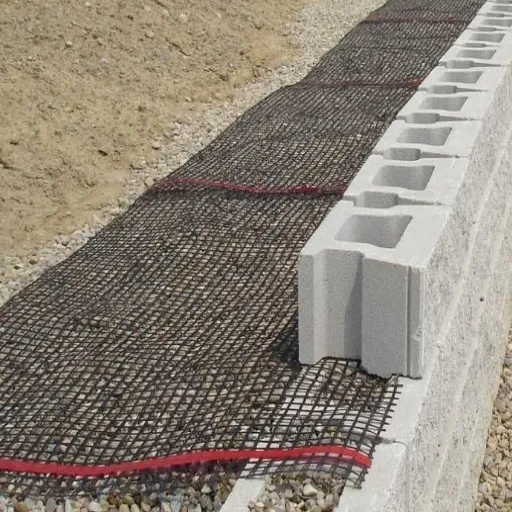
The reinforcement type shapes the entire design, because inextensible and extensible reinforcement behave so differently. Your choice also drives the critical failure surface and the internal coefficient K_r used in the analysis.
Inextensible Reinforcement: Steel
Steel strips and welded wire mesh are inextensible. They barely stretch before they carry load, so they mobilize soil strength quickly. Their weakness is corrosion, which makes electrochemical fill properties, resistivity, pH, chloride, and sulphate content, a hard design constraint. Steel dominates in bridge abutments and rail applications where its stiffness is valuable.
Extensible Reinforcement: Geogrid and Geotextile
Polymer geogrids and woven geotextiles are extensible. They stretch several percent before failing, which means they engage the soil more gradually but are immune to corrosion and can be designed for a 75 to 120-year life. For most walls and slopes, an extensible geogrid is the practical choice.
Why Aperture Size Matters
For interlock to work, aggregate particles must lodge in the grid apertures. If the apertures are too large relative to the aggregate, the particles pass through and the interlock is weak. The common guidance is an aperture roughly 1.2 to 1.6 times the nominal aggregate size. This is a design decision, not an afterthought, and it is covered in detail in the geogrid aperture size guide. Get it wrong and the composite action that reinforced soil design depends on never fully develops.
When the target reinforcement is a fabric rather than a grid, the comparison turns on function. A geotextile provides separation, filtration, and drainage in addition to tensile capacity, while a geogrid provides higher tensile stiffness through interlock. Many designs use both. The trade-offs are set out in the geogrid vs geotextile comparison, and the full test-value tables sit in our geogrid specifications and ASTM standards reference.
Reinforced Soil Design Software & Analysis Methods
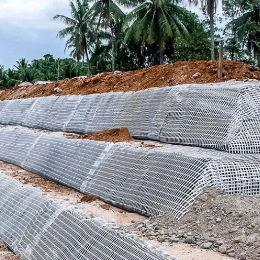
Most reinforced soil design is done in limit-equilibrium software, which assumes a failure surface and compares driving and resisting forces or moments. The reinforcement layers that intersect the surface add resisting force, and the design is iterated until the target factor of safety is reached.
The main tools are ReSSA, developed for the FHWA specifically for reinforced soil slopes, and GeoStudio SLOPE/W, a broad limit-equilibrium platform with reinforcement libraries from major suppliers. MSEW is used for wall design, and Maccaferri’s MacStars supports system-specific analysis. The underlying methods include Bishop for circular surfaces and Spencer and Morgenstern-Price for rigorous equilibrium, and two- or three-part wedge mechanisms for direct sliding and translation.
Finite-difference methods such as FLAC are used for complex, tiered, or seismic problems, and they generally agree with limit-equilibrium results as the factor of safety approaches one. The choice of tool matters less than the discipline of using it. Verify that the software models the reinforcement strength as a design strength, not an ultimate strength, and that the reduction factors match the code you are designing to.
Seismic Design of Reinforced Soil Structures
Reinforced soil performs well under seismic loading, and this is one of its underappreciated advantages. Because the reinforced mass is ductile and has no tensile weakness, it tolerates the deformation that shakes rigid concrete walls apart. FHWA guidance notes that reinforced soil structures show greater seismic resistance than rigid concrete structures.
The simplest method applies a pseudo-static horizontal force to an earth-pressure analysis, the Mononobe-Okabe approach. For more complex structures, including tall walls on soft ground, design shifts to a generalized limit-equilibrium stability analysis that captures the dynamic response more faithfully. Wrapped high-fill embankments and bridge abutments are the cases where seismic loading most often governs the reinforcement layout.
Seismic design is a specialty within reinforced soil design, and the reinforcement demand can rise sharply in high-hazard regions. The geogrid seismic design guide covers the methods, the loading assumptions, and the cases where seismic detail controls the specification.
Design Deliverables, Responsibility & QA/QC
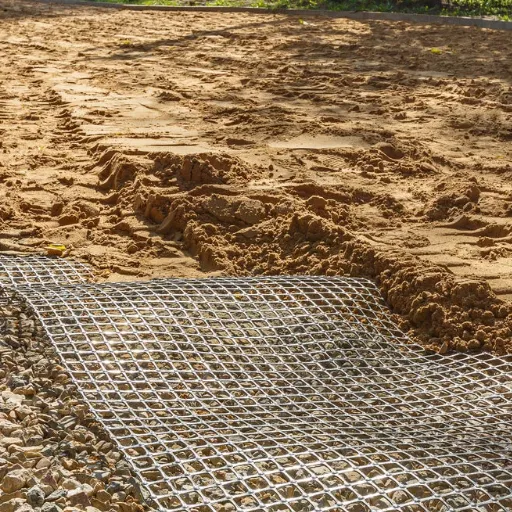
A reinforced soil design is only as good as what gets documented and built. Design responsibility is frequently shared between the engineer of record and the reinforcement supplier, and gaps between the two are a common source of failure. Agree the split at the start and put it in writing.
The design deliverables should show the reinforcement type, strength, length, and spacing for every layer, the connection detail at the facing, the drainage system, and the fill specification, along with the design basis and the factors of safety achieved. On the construction side, the hold points matter as much as the drawing. Fill gradation and compaction, typically to at least 95 percent of maximum dry density, reinforcement overlap and connection checks, and drainage inspection should all be verified before the next lift goes down.
Durability closes the loop. Steel reinforcement demands attention to corrosion and electrochemical fill limits. Polymer reinforcement demands attention to installation damage, UV exposure before cover, and creep. A structure that meets its factors of safety on paper but skips these checks has not been designed for its design life.
Common Reinforced Soil Design Mistakes to Avoid
Most reinforced soil failures trace back to a handful of design errors, and almost all of them are avoidable.
- Trusting software output blindly. Read the warning messages, verify the reduction factors, and keep terminology consistent with the cited code.
- Wrong reinforcement type or orientation. A biaxial grid in a wall, or a uniaxial grid installed with its strong axis parallel to the face, wastes capacity. Orientation is a design instruction, not a site preference.
- Reinforcement cut short. If the grid does not extend past the governing failure surface with enough embedment, it pulls out.
- Inadequate drainage. Water is the enemy of every wall. Poor drainage can double the earth pressure the structure was designed to resist.
- Poor fill control. Fines content, plasticity, and gradation must fall within the code’s limits. Importing the wrong fill can invalidate the design.
- Durability omitted. Corrosion for steel, creep, UV, and installation damage for polymers must all be accounted for.
- Unclear design responsibility. Gaps between the designer and the supplier leave no one accountable for the interface.
The forensic detail behind these failures, and the mechanisms that produce them, is covered in the geogrid failure modes guide. Study it before you sign a design, not after a wall moves.
Cost & Sustainability: Reinforced Soil vs Concrete
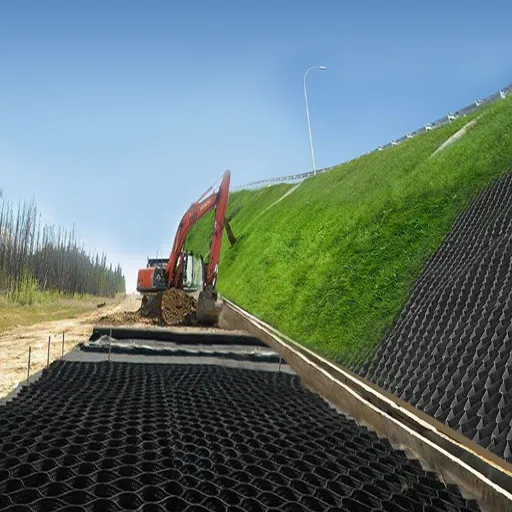
Reinforced soil design is not only technically sound, it is usually the economical choice. Geosynthetic-reinforced walls commonly cost 30 to 60 percent less than concrete gravity or cantilever walls, and geogrid veneer systems have been shown to save up to USD 403 per square meter against gravity walls. An independent 2025 study found MSE walls carried up to 98 percent less embodied carbon than concrete retaining walls.
The savings come from what you no longer build. There is no formwork, no curing time, no reinforcement cage, and frequently no deep structural footing, because the flexible structure tolerates minor settlement and spreads load into the reinforced fill. Construction is faster, mobilization is lighter, and on-site soil often replaces imported material.
Honesty matters here. The advantage narrows at greater wall heights, and studies disagree on whether it grows or shrinks with height. High-faced walls may need select granular fill imported at cost, and hidden excavation and backfill for reinforcement embedment can add to the total. For tall or heavily loaded structures, compare the full installed cost, not the roll price. Our geogrid cost per square meter guide breaks down the numbers.
Ready to price a reinforced soil structure? Send your geometry and loading, and request a technical quote with a specification that matches your governing code.
How to Specify & Source Reinforced Soil Materials
Reinforced soil design produces requirements, and procurement turns those requirements into a supply. The order of operations matters: lead with the design outputs, then find the material that satisfies them.
- Lead with the design outputs. Provide the strength class, length, spacing, and type from the analysis, not a product name.
- Verify the material meets the code. Confirm ultimate and long-term design strength at 2 and 5 percent strain, minimum average roll values, junction efficiency of at least 90 percent, and carbon black content for UV resistance.
- Confirm durability data. Request creep reduction factors, corrosion data for steel, and the UV exposure window for polymer reinforcement.
- Agree the responsibility split. Document who designs what, and request certified test reports.
- Qualify the supplier. Check export capability, minimum order flexibility, technical consultation, and quality certification.
For projects that cross borders, supply reliability and technical support matter as much as price. Our geogrid reinforcement for walls and earthworks range is export-ready, and when a design calls for a fabric companion for filtration and drainage, our woven geotextile separation and drainage layers round out the specification.
Frequently Asked Questions
What is reinforced soil design?
Reinforced soil design is the engineering process that combines compacted soil fill, horizontal layers of tensile reinforcement, and a facing into a composite structural mass, then verifies that the mass resists internal rupture and pullout and external sliding, bearing, and global failure with an adequate factor of safety.
How do you design a reinforced soil wall?
Establish the geometry and loads, determine the soil properties, select the reinforcement, check the unreinforced case, then design for internal stability (rupture and pullout) and external stability (sliding, bearing, eccentricity, global). Iterate the reinforcement layout until every check meets its target safety factor.
How do you design a reinforced soil slope?
Reinforced soil slope design starts with the same geometry, soil-property, and loading steps as a wall, then switches to a limit-equilibrium stability analysis. Check circular and wedge surfaces through and behind the reinforced zone, size the reinforcement to lift the factor of safety to the target (typically 1.5), and confirm external and global stability of the reinforced mass.
What factor of safety is required for a reinforced soil wall?
Under FHWA allowable stress design, typical targets are 1.5 for sliding, 2.0 for bearing capacity, 1.5 for global stability, and 1.5 for pullout. Under AASHTO LRFD or BS 8006-1, the same safety is expressed as resistance or partial factors, so always match the framework to the governing code.
What is the difference between MSE and GRS walls?
An MSE wall uses connected facing units such as segmental blocks or panels with structurally designed connections. A GRS wall uses closely spaced reinforcement, no more than about 300 mm, where the facing needs no structural connection because the closely spaced layers confine the soil itself.
How long should reinforcement be in a reinforced soil wall?
A common starting value is about 0.7 times the wall height, with a minimum of about 3 ft. The governing length comes from the analysis: the reinforcement must extend past the critical failure surface with enough embedment to develop the required pullout resistance.
What is T_al, the long-term design strength?
T_al is the allowable design strength of the reinforcement, calculated as the ultimate tensile strength divided by the product of installation damage, durability, and creep reduction factors. It is typically only 33 to 50 percent of the ultimate strength, so specifying against the ultimate number over-estimates capacity.
What is the pullout resistance factor for geogrid?
For a geogrid in granular soil, the pullout resistance factor F* is approximately 0.8 tan(phi’), higher than the two-thirds tan(phi’) used for geotextiles because geogrid transverse ribs develop passive bearing as well as skin friction. Pullout capacity is verified with the ASTM D6706 test.
What software is used for reinforced soil design?
Common tools include ReSSA for reinforced soil slopes and GeoStudio SLOPE/W for general limit-equilibrium analysis, with MSEW for walls and MacStars for system-specific work. These use methods such as Bishop, Spencer, and Morgenstern-Price, and finite-difference models like FLAC are used for complex or seismic cases.
Is a reinforced soil wall cheaper than concrete?
Usually, yes. Geosynthetic-reinforced walls commonly cost 30 to 60 percent less than concrete gravity or cantilever walls, and can cut embodied carbon by up to 98 percent. The advantage narrows at greater wall heights and depends on soil conditions, so compare total installed cost rather than roll price.
Conclusion
Reinforced soil design is a discipline, and it rewards a disciplined approach. Soil carries compression; reinforcement supplies the tension soil lacks; together they form a composite mass that can hold a slope, support a bridge, or retain a highway cut. But the composite only works when the design is right.
The essentials are consistent from a garden wall to a towering abutment. Select the governing code and follow it. Confirm reinforcement is needed and locate the critical surface. Check internal stability for both rupture and pullout, using the long-term design strength rather than the ultimate. Check external stability for sliding, bearing, eccentricity, and global failure. Respect the spacing and length rules that the analysis produces, and never omit drainage or durability. Then document the design so it can be built and verified.
Every one of those steps is a place where a shortcut becomes a failure, and every failure we described came from a design gap, not a material gap. Get the design right and the materials will perform for generations. Get it wrong, and no grid is strong enough to save the structure.
If you are specifying reinforced soil materials or want an engineering review of a design, our team supplies export-ready geogrid and geotextile reinforcement with technical consultation and flexible order quantities. Request a technical quote or contact our engineering support to match the right reinforcement to your reinforced soil design.