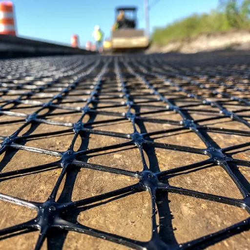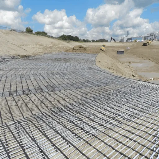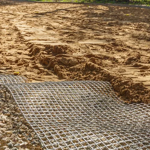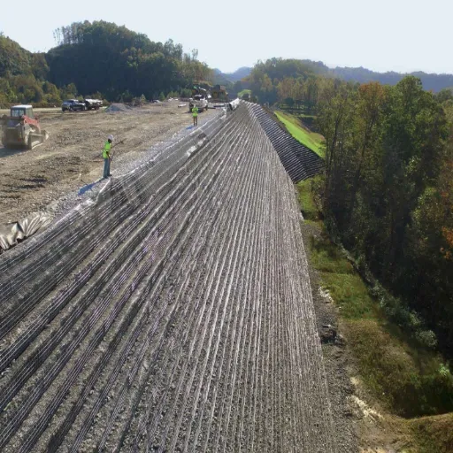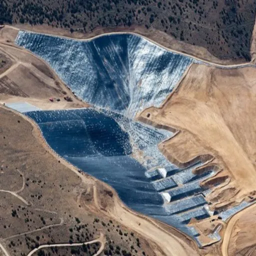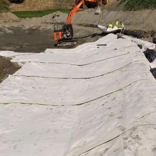
A geogrid retaining wall is a mechanically stabilized earth (MSE) structure in which horizontal layers of high-tensile uniaxial geogrid are laid into compacted backfill and connected to a facing, so the face, soil, and reinforcement act as a single gravity mass. It is the cost-effective, code-compliant alternative to a concrete gravity wall for most walls above 1.2 m (4 ft), and it typically costs 20 to 50 percent less than poured concrete.
Ask the contractor who learned that lesson in 2021. A crew in Colorado quoted two options for a 3 m (10 ft) backyard wall: a poured concrete cantilever at USD 68,000, or a segmental block MSE wall with uniaxial geogrid at USD 41,000. They took the geogrid option, saved 40 percent, and finished in nine days instead of four weeks. The wall has held through three freeze-thaw winters without a crack. The savings came from a simple fact: the geogrid turns cheap, compacted soil into the structural mass, so there is no deep footing, no formwork, and no rebar.
That pattern repeats on highway abutments, mining berms, and residential slopes worldwide. This guide explains how a geogrid retaining wall works, why uniaxial geogrid is the only efficient reinforcement for walls, the design outputs an engineer actually calculates, the strength classes to specify, a step-by-step installation sequence, and honest cost expectations. Whether you are an engineer, a contractor, or a procurement buyer, you will finish knowing how to specify and buy this wall system with confidence.
Key Takeaways
- A geogrid retaining wall is an MSE structure: uniaxial geogrid layers in compacted backfill turn soil into a gravity mass, eliminating the need for a deep concrete footing.
- Uniaxial geogrid is the correct reinforcement for walls because the load runs in one direction; biaxial grids spend half their polymer on a direction the wall does not load.
- Layer spacing, embedment length, and required grid strength are engineering design outputs, not rules of thumb; typical values are 16 to 24 in spacing and 0.6 to 1.0 times the wall height for embedment.
- Geogrid reinforcement is generally required for walls above 1.2 m (4 ft), or with surcharge loads, weak backfill, or a slope above the crest.
- Installed MSE walls run roughly USD 30 to 75 per square foot of face, with 20 to 50 percent savings over concrete for most sites; the geogrid itself adds only 8 to 15 percent of wall cost.
What Is a Geogrid Retaining Wall?
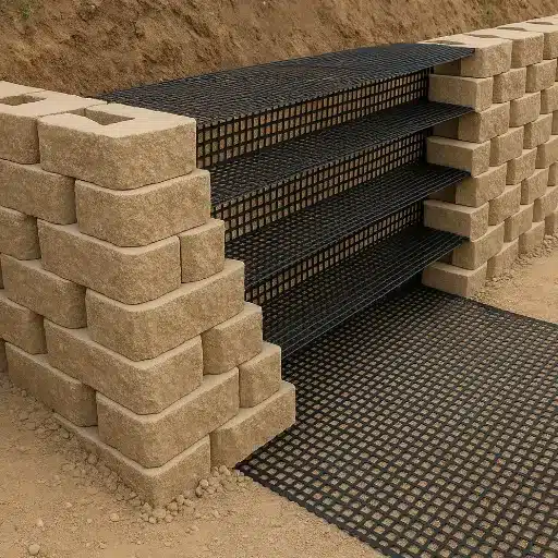
A geogrid retaining wall is a reinforced-soil structure in which horizontal layers of high-tensile polymer geogrid are embedded in compacted granular backfill and connected to a facing unit, creating a mechanically stabilized earth (MSE) mass that resists overturning and sliding as a single gravity body.
The key idea is that the wall works as a mass, not a face. Every geogrid layer is held in tension and pulls the facing back into a soil mass far heavier than the face itself. The reinforced soil block, not the masonry or concrete panel, resists the lateral earth pressure. This is why a geogrid wall can stand without the deep, heavily reinforced footing a conventional concrete wall needs.
The system has four components:
- Facing: precast concrete panels, segmental concrete blocks, or a wrapped geogrid face that can be vegetated.
- Reinforcement: layers of uniaxial geogrid extending from the facing back into the fill.
- Backfill: well-graded, free-draining granular soil compacted in thin lifts.
- Drainage: a perforated pipe and aggregate column behind the wall that removes groundwater.
A common misconception is that the wall face carries the load. It does not. In an MSE wall, the face is a shell that holds the soil in place and transfers tension into the grid. The soil and grid do the structural work. If you are new to the broader family of materials, our complete geogrid guide to types and applications covers the full picture, including biaxial and triaxial variants.
Why Uniaxial Geogrid Is the Right Reinforcement for Retaining Walls
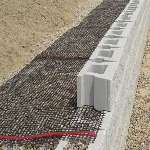
Choose uniaxial geogrid for any retaining or MSE wall. It is the only efficient reinforcement for this application, and the reason is the direction of the load.
The Load Runs in One Direction
Lateral earth pressure acts roughly perpendicular to the wall face, pulling the soil mass away from the wall along a predictable plane. That tensile demand is essentially one-directional. A uniaxial geogrid is punched and drawn in the machine direction only, aligning the polymer molecules along that axis and producing very high tensile strength with low elongation and low long-term creep.
A biaxial grid has balanced strength in two directions, which is exactly what a road base needs. Against a wall, half of that strength is pointing in a direction the wall never loads. You would pay for strength you cannot use, and you might need more layers to compensate. Install the uniaxial grid with its strong axis perpendicular to the wall face; if you orient it wrong, you cut the reinforcement effect dramatically.
Creep Resistance Under Sustained Load
Walls hold constant tension for decades. Creep, the slow elongation of polymer under sustained load, is the single most important long-term performance metric for wall reinforcement. Uniaxial geogrids are designed for this duty. Polyester (PET) grids show the lowest creep, followed by high-density polyethylene (HDPE) and polypropylene (PP), and engineers account for it with a creep reduction factor when they calculate long-term design strength.
Uniaxial vs Biaxial at a Glance
| Feature | Uniaxial geogrid | Biaxial geogrid |
|---|---|---|
| Strength | One direction (machine) | Balanced, both directions |
| Aperture shape | Elongated / rectangular | Square / rectangular |
| Typical strength | 30 to 400+ kN/m (MD) | 15 to 50 kN/m each way |
| Best for | Retaining/MSE walls, slopes, abutments | Road base, subgrade, working platforms |
| Orientation risk | Must align strong axis perpendicular to face | Less sensitive |
For road and pavement applications, where loads arrive from every direction, a biaxial or triaxial grid is the right tool. That choice is covered in depth in our biaxial vs triaxial geogrid comparison.
Geogrid Retaining Wall Design: The Outputs an Engineer Calculates
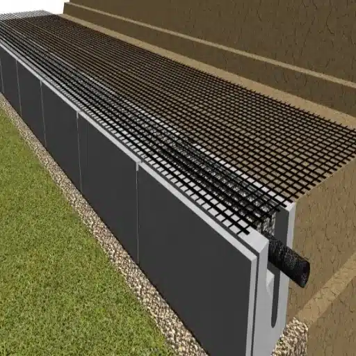
Layer spacing, embedment length, and required grid strength are engineering design outputs. They come from a stability analysis based on wall height, backfill friction angle, groundwater, surcharge, and the facing system, and they change up the height of the same wall. Spacing typically tightens toward the base, where earth pressure is highest. There is no rule of thumb that survives contact with a real site, so a wall of consequence needs a designed and permitted wall.
That said, the numbers below give you a practical starting reference and help you check a supplier’s or engineer’s work.
When Is Geogrid Required?
Per FHWA-NHI-10-024 geosynthetic design guidelines and the NCMA Segmental Retaining Wall Design Manual, geogrid reinforcement is generally required when any of these conditions apply:
- Wall height exceeds 1.2 m (4 ft).
- A surcharge sits above the wall: buildings, driveways, fences, hot tubs, or heavy planters.
- The backfill is weak or cohesive: clay, silt, or organic soil with a low friction angle.
- A slope rises above the crest, which raises lateral pressure.
- Drainage is poor, so trapped water adds hydrostatic pressure.
Below about 0.9 m (3 ft), with clean granular backfill and no surcharge, a wall may not need reinforcement. The NCMA manual still recommends an engineering review above 0.9 m (3 ft), and most installers add at least one base layer for any wall built in clay soil.
Layer Spacing
Vertical spacing typically falls between 400 and 600 mm (16 to 24 in), which usually means a grid layer every two to three block courses. The grid must land on a block joint so it connects cleanly to the facing.
| Wall height | Typical layers | Notes |
|---|---|---|
| Under 0.9 m (3 ft) | Optional | Decorative only, unless a load or slope is present |
| 0.9 to 1.5 m (3 to 5 ft) | 1 to 2 | Review for clay backfill or any surcharge |
| 1.5 to 2.1 m (5 to 7 ft) | 2 to 3 | Standard residential |
| 2.1 to 3 m (7 to 10 ft) | 3 to 5 | Engineered design recommended |
| Over 3 m (10 ft) | Full design | Professional engineering required |
Embedment Length
The grid must extend past the potential failure surface into stable ground. Practical guidance puts embedment at 0.6 to 1.0 times the wall height (0.7 to 1.0 is common, 0.75 with a surcharge), with an absolute minimum around 1.2 m (4 ft). A 2 m wall, for example, needs roughly 1.2 to 1.6 m of geogrid length measured from the back of the face. Cut-short embedment is one of the most common causes of wall movement, so this is not a place to save material.
Required Tensile Strength & Long-Term Design Strength
Buyers and specifiers get confused here because suppliers quote ultimate tensile strength (UTS) while engineers design with long-term design strength (LTDS). The LTDS is the UTS divided by reduction factors for installation damage, creep, and durability, and it is typically 33 to 50 percent of the UTS. When a supplier quotes a “120 kN/m grid,” an engineer is really working with roughly 40 to 60 kN/m of usable long-term strength. The relevant test is ASTM D6637, and the LTDS method is GRI-GG4.
As a starting reference for required UTS in the machine direction:
| Grid strength (UTS, machine direction) | Typical use |
|---|---|
| 20 kN/m | Low walls, ideal soil |
| 35 to 55 kN/m | Standard residential walls |
| 80 to 120 kN/m | Engineered and commercial walls |
| Over 150 kN/m | Tall or heavily loaded walls, bridge abutments |
The design also depends on the soil-grid interface. Backfill should be granular and free-draining, not clay, and the maximum design friction angle is capped at 34 degrees per FHWA and AASHTO guidance. The pullout resistance factor for a geogrid in granular soil is commonly estimated as 0.8 times the tangent of the friction angle. If you want the full step-by-step framework for moving from project requirements to a specification, our how to choose a geogrid selection framework walks through it.
Uniaxial Geogrid Strength Classes & Specifications
Uniaxial geogrids come in three polymer families, each with distinct creep and durability characteristics. Strength is reported in the machine direction, and the values below are typical published ranges.
| Polymer | Manufacturing | Typical strength range | Creep performance | Best wall use |
|---|---|---|---|---|
| Polypropylene (PP) | Punched and drawn | 60 to 300 kN/m | Moderate | Cost-effective walls, moderate heights |
| High-density polyethylene (HDPE) | Punched and drawn | 60 to 200 kN/m | Low | Standard MSE walls, strong long-term data |
| Polyester (PET) | Woven/knitted yarns, coated | 50 to 400+ kN/m | Very low | Tall walls, abutments, heavy load |
Two numbers matter most when you verify a datasheet. First, junction efficiency is the ratio of strength at the junction to the strength of the rib itself. It should be at least 90 to 93 percent, because load transfers from soil into the grid at the junctions, and weak junctions mean the grid cannot mobilize its rib strength. Second, carbon black content should be at least 2 percent for PP and HDPE grids so they survive UV exposure during construction, per ASTM D4218. PET grids rely on a protective coating instead.
A practical check when you buy: request the Minimum Average Roll Value (MARV) test report for the grade, and confirm the tensile values at 2 percent and 5 percent strain, not just the ultimate value. Engineers design against serviceability limits at low strain, so the strength at 2 percent and 5 percent strain tells you how the wall behaves under working load.
Geogrid Retaining Wall Installation: Step-by-Step
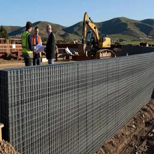
The construction sequence is the same on every job. The dimensions change with the design, but the order does not.
- Prepare the site and foundation. Locate utilities, excavate a leveling trench 150 to 200 mm (6 to 8 in) below the first course, and place 19 mm (3/4 in) drainage gravel. Compact the sub-base to at least 95 percent Standard Proctor density, and remove any organic or poor soil.
- Build the leveling pad and first course. The pad must be dead level front to back and side to side; small errors get exaggerated as the wall rises. Lay the first block course on line and level.
- Backfill and compact to the first grid level. Fill behind the first courses in thin lifts, no more than 200 mm (8 in), and compact each lift. Within 0.3 to 0.9 m (1 to 3 ft) of the face, use only hand-operated compaction so you do not shove the blocks out of line.
- Roll out the geogrid. Cut the grid to the designed embedment length and place it on a block joint, with the machine direction running back into the fill, perpendicular to the face. Connect or clip it at the facing. Pull it hand-taut to remove wrinkles and stake it back. Never overstretch the grid, and never allow gaps between adjacent sheets larger than about 50 mm (2 in).
- Lock in and backfill over the grid. Place the next block course over the grid to lock it, fill the block cores, and backfill to the designed length. Spread fill forward off already-placed material instead of tracking equipment on the exposed grid. Compact in thin lifts, working from the face outward.
- Install drainage. Place a 100 mm (4 in) perforated drain pipe at the lowest point behind the wall, with outlets every 9 to 15 m (30 to 50 ft) on a positive slope. Add a 300 mm (12 in) column of clean drainage aggregate and a geotextile filter between the soil and the stone. Slope the grade above the wall away from the crest at least 2 percent.
- Repeat to the top and cap. Keep the wall about four courses ahead of the fill, and do not allow vehicles on exposed grid without at least 150 mm (6 in) of cover. Cap the top course and backfill to finish grade.
Drainage is not optional. Water is the number one cause of retaining wall failure, and even a reinforced wall fails when hydrostatic pressure builds behind it.
Video tip: Watch a commercial MSE wall being built once before your crew starts. A single site visit shows the leveling pad, the block connection, and the compaction rhythm far better than any drawing.
Geogrid Retaining Wall Cost: What to Budget
The geogrid material itself is inexpensive: roughly USD 0.50 to 8.00 per square meter depending on strength, which is usually only 8 to 15 percent of total wall cost. The structural gain from that small spend is large, which is why contractors report walls strengthening 300 to 600 percent for a fraction of the cost of concrete.
Installed wall costs, based on published 2026 pricing, land in these ranges:
| Wall system | Installed cost per square foot of face |
|---|---|
| Geogrid-reinforced segmental block | USD 20 to 40 |
| MSE wall (precast panel) | USD 30 to 75 |
| Poured concrete | USD 30 to 60+ |
The savings story is real but not universal. Sources commonly report 20 to 50 percent savings versus concrete, driven by less material, no formwork, no deep footing, and faster installation. A residential contractor in the example at the top of this guide saved 40 percent on a 10 ft wall. Naue, a global geosynthetics manufacturer, reports up to 40 percent savings versus concrete gravity walls and even larger savings for veneer wall systems.
Be honest about the caveats, because they change the math:
- Walls under 0.9 m (3 ft) save little, because the concrete option is small too.
- Rocky substrate adds excavation cost.
- Saturated soils require more drainage work.
- Grid embedment reaches 60 to 100 percent of wall height into the slope, and that extra excavation and backfill is easy to overlook in a budget.
For a taller wall (over 4.5 m / 15 ft), geogrid and MSE systems are consistently the most economical option, which is why highway departments specify them for high retaining structures.
Geogrid Retaining Wall Applications Beyond the Backyard
The same system that holds up a residential slope carries some of the largest structures in civil engineering.
Bridge abutments and approaches. Uniaxial geogrid reinforcement allows a compacted fill embankment to act as the abutment, carrying approach traffic and eliminating the need for piling in many cases. Highway agencies use this to shorten schedules and cut cost.
Highway widening and two-stage walls. On soft soils, an MSE wall can be built in two stages so the first stage settles before the second is built. A rigid concrete wall tolerates that settlement far less gracefully.
Mining embankments and landfill berms. High-strength PET or HDPE grids reinforce steep berms under heavy machinery and long-term waste loads. A 26.95 m (88 ft) tiered MSE wall in Indonesia, reinforced with high-strength uniaxial geogrid, met a static factor of safety of 1.301 and a seismic factor of safety of 1.163 under a 375 kPa surcharge.
Steep slopes and vegetated faces. With wrapped geogrid facing, near-vertical walls at 85 degrees or steeper can be built and vegetated for a green facade. That application overlaps with slope and embankment work, covered in our geogrid for slopes and embankments guide.
Detention ponds and pressure-relief walls. Low, reinforced walls contain stormwater ponds and relieve pressure around existing structures.
In every case, the procurement requirement is the same: a supplier who can provide the strength grade you specified, with test data, at export-friendly order volumes. That is where a global geosynthetics supplier comes in. Our team supplies uniaxial geogrid reinforcement for walls and earthworks in PP, HDPE, and PET, with flexible minimum order quantities and engineering support for specification.
Common Geogrid Retaining Wall Failures & How to Avoid Them
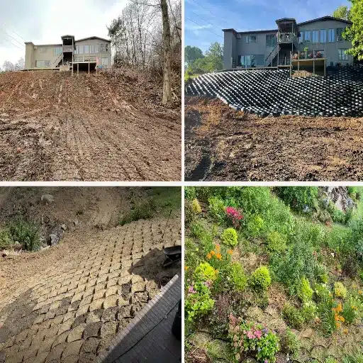
Most geogrid wall failures trace back to five field mistakes. Knowing them in advance is cheaper than fixing them later.
1. The wrong grid, or the right grid in the wrong orientation. Biaxial geogrid against a wall, or a uniaxial grid with its strong axis parallel to the face, neutralizes the reinforcement. When a Texas crew installed a uniaxial grid with the strong direction running parallel to a 4 m wall face in 2023, the effective strength dropped by roughly 70 percent, the facing bulged within eight months, and the wall was rebuilt at more than double the original cost.
2. Grid cut short. If the embedment does not reach past the failure plane into stable ground, the wall rotates or slides. Embedment is a design output; do not value-engineer the layer length.
3. Poor compaction. Reinforcement only mobilizes through friction and interlock with dense soil. Contractors say compaction is 50 percent of the wall’s strength. Sloppy compaction causes settlement and bulging within one to three years.
4. Missing drainage. Water doubles soil pressure and softens the fill. Walls fail from behind, not from the front, so the drain pipe and aggregate column are structural, not optional.
5. Too few layers or the wrong grade. Value-engineering layers to save a few dollars typically ends with a failed wall and a much larger rebuild bill.
A simple QA/QC checklist prevents all five. Verify the MARV test report matches the specified grade, confirm junction efficiency is 90 percent or higher, check carbon black at 2 percent or more, keep the grid taut and cover it within 48 hours, and confirm the compaction and drainage before you sign off.
Frequently Asked Questions
Is geogrid necessary for a retaining wall?
Generally yes for walls above 1.2 m (4 ft), or with a surcharge, weak backfill, or a slope above the crest. Below about 0.9 m (3 ft) on well-drained granular soil, reinforcement may be optional.
How many layers of geogrid do I need for a retaining wall?
Typical engineered walls use two to four layers at 400 to 600 mm (16 to 24 in) vertical spacing. A 1.8 m (6 ft) wall in clean sand may need three layers; the same wall in clay with a slope surcharge may need five.
How far should geogrid extend behind a retaining wall?
Roughly 0.6 to 1.0 times the wall height, with a minimum around 1.2 m (4 ft). The grid must pass the potential failure surface into stable ground.
What is the difference between uniaxial and biaxial geogrid?
Uniaxial geogrid has high strength in one direction and is used for walls, slopes, and abutments. Biaxial geogrid has balanced strength in two directions and is used for roads and working platforms.
Can geogrid build a retaining wall without concrete?
Yes. An MSE wall needs no deep concrete footing. The facing can be segmental blocks or a vegetated wrapped face, and the reinforced soil carries the load.
How much does a geogrid retaining wall cost?
Installed costs typically run USD 30 to 75 per square foot of face, often 20 to 50 percent below poured concrete for larger walls.
Conclusion
A geogrid retaining wall is a reinforced-soil structure that works as a mass, not a face. Uniaxial geogrid layers in compacted backfill do the structural work, and that simple idea cuts cost, speeds construction, and removes the deep concrete footing that conventional walls require. Specify the right grid orientation, let an engineer set the spacing and embedment, verify the long-term design strength, and never skip the drainage.
If you are specifying or buying a geogrid retaining wall, the winning sequence is: define the wall height and loads, have an engineer produce the design outputs, then source a grid that meets the specified MARV values with test data to back it. A supplier with engineering consultation makes that last step painless.
Ready to move forward? Request a technical quote from our engineering team, or tell us your wall height and soil conditions and we will help you specify the right uniaxial geogrid grade.