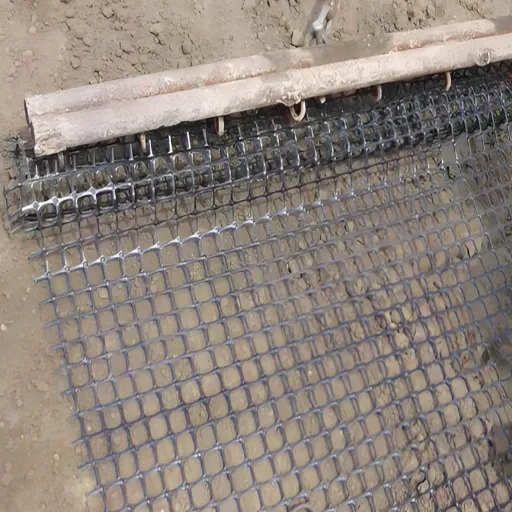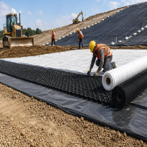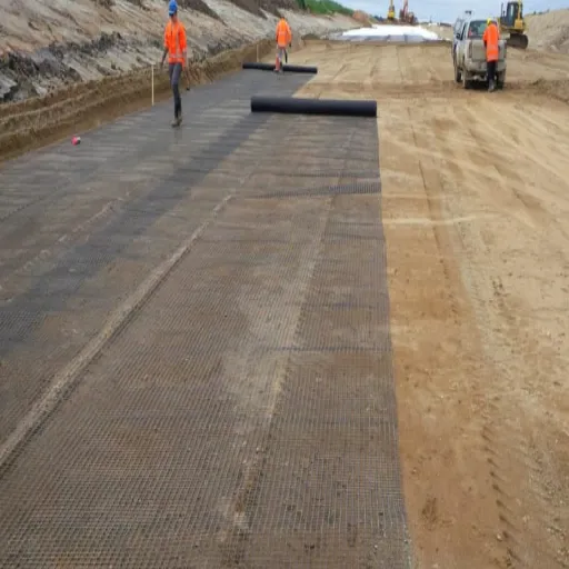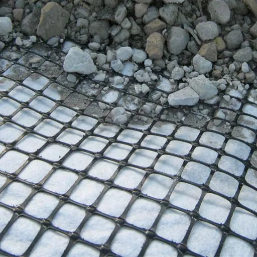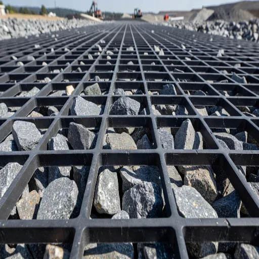
Geogrid reinforcement raises the bearing capacity of a shallow foundation by a factor of 1.5 to 3, expressed as the bearing capacity ratio (BCR). That range comes from model and field footing tests published by the Louisiana Transportation Research Center. The gain depends less on which grid you buy than on where you put it: first layer at 0.33B below the footing, layers spaced at 0.33B, reinforced depth of 1.5B, and layer length of 5B, where B is the footing width.
Most pages that discuss geogrid bearing capacity stop at “geogrid increases bearing capacity.” That sentence is true and useless. You cannot design with an adjective.
What you need is the number, the layout that produces it, and an honest answer about whether capacity is even the check that governs your footing. This guide gives all three. It draws on a 41-page Federal Highway Administration research report and the FHWA shallow foundations circular, and it separates the foundation problem from the pavement problem that shares the same keyword.
Key Takeaways
- Geogrid bearing capacity is measured as BCR, the ratio of reinforced to unreinforced ultimate capacity. Published test results give a range of 1.5 to 3.
- Four layout parameters control the result:
u/B(first layer depth),h/B(layer spacing),d/B(reinforced depth), andl/B(layer length). Recommended values are 1/3, 1/3, 1.5, and 5.- The gain is mobilised at settlement. A BCR of 2.4 is not a free 2.4x at zero movement. The footing has to deflect to develop it.
- Settlement usually governs, not capacity. FHWA guidance limits bearing stress so total settlement stays near 25 mm (1 in).
- Specify geogrid by tensile modulus at 2% strain, not ultimate tensile strength. Two grids with identical ultimate strength can deliver very different bearing capacity.
What Is Geogrid Bearing Capacity?
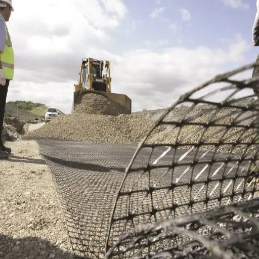
Geogrid bearing capacity is the increase in the ultimate bearing capacity of a soil mass caused by horizontal geogrid layers, expressed as a ratio to the unreinforced case. That ratio is the bearing capacity ratio, BCR. A BCR of 2.0 means the reinforced foundation carries twice the pressure of the same foundation without reinforcement.
Two different engineering problems share this keyword, and confusing them is the most common source of bad numbers.
Shallow foundations and reinforced soil foundations (RSF). A footing or spread base sits on reinforced soil. The governing dimension is the footing width, B. The performance measure is BCR. This is the subject of this article.
Pavements and working platforms. A wheel or track load crosses a stabilised granular layer. The governing dimension is the subgrade CBR, and the performance measures are rut depth, traffic benefit ratio, and layer thickness savings. That is a different problem with different design methods. Our geogrid for soft ground guide covers it in full.
Why the distinction matters: a vendor quoting “bearing capacity improvement” may be citing a pavement test, a plate load test, or a footing test. Those are not interchangeable. Ask which one before you accept the number.
If you want the particle-scale mechanics behind the gain, our guide to how geogrid works covers interlock, passive bearing on transverse ribs, and the soil-geogrid interaction model. This article assumes that mechanism and moves to quantification.
How Reinforcement Raises Bearing Capacity
The conceptual relationship is simple. Reinforced capacity equals unreinforced capacity plus a contribution from the reinforcement:
q_u(R) = q_u(UR) + q_T
Here q_u(R) is the ultimate bearing capacity of the reinforced foundation, q_u(UR) is the unreinforced value, and q_T is the added capacity generated by tension in the reinforcement layers. The LTRC report develops this into full analytical solutions for clay, sand, and crushed limestone. For design, the important part is that the second term exists and that its size is governed by layout.
The failure mode changes
Reinforcement does not simply scale up the unreinforced failure surface. It alters it.
The research identified five possible failure modes for a reinforced soil foundation. Two are avoidable by layout alone: failure above the top reinforcement layer, and failure between layers. Both are prevented by keeping the top layer spacing u and the vertical spacing h below 0.5B.
The governing mode for cohesive soil is more interesting. A punching shear failure develops through the reinforced zone, followed by a general shear failure in the unreinforced soil beneath it. The mechanism was adapted from Meyerhof and Hanna’s 1978 solution for a strong layer over a weak layer, modified to include the upward shear that reinforcement tension adds along the punching surfaces.
That is why the reinforced depth matters so much. The reinforcement is not holding the whole failure mass together. It is converting one failure mode into a less severe one, and it can only do that within its own depth.
Confinement or membrane effect, depending on the soil
Two mechanisms contribute, and which one dominates depends on the fill.
In reinforced clay and sand, the reinforcement sits close to horizontal at ultimate load. The dominant mechanism is confinement: the grid restrains lateral movement of the soil directly above and below it.
In reinforced crushed limestone, the particles are large enough to move with the grid. There the dominant mechanism is the membrane effect, where the reinforcement acts in tension across a deflected surface. Our article on the tensile membrane effect covers when that tension actually mobilises. The short version: it needs deformation, which is why it matters most on unpaved and temporary surfaces.
Specifying a grid and unsure which mechanism you are relying on? Our engineering team can review your subgrade and fill together and tell you which one governs. Request a technical review.
The Four Layout Parameters That Decide the Result
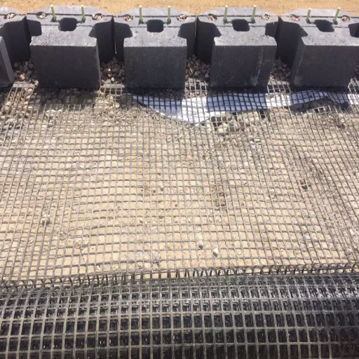
This is the part competitors do not publish. Every layout decision that governs geogrid bearing capacity reduces to four distances, each normalised by the footing width B.
uis the depth from the footing base to the first reinforcement layer.his the vertical spacing between layers.dis the total depth of the reinforced zone.lis the length of each reinforcement layer.
The recommended values below come from LTRC Report FHWA/LA.08/423, Table 5, based on model and large-scale field footing tests across three soil types.
| Parameter | Typical range | Recommended | What it controls |
|---|---|---|---|
u/B |
0.2 – 0.5 | 1/3 | Mobilisation of the top layer; below 0.5B prevents failure above the grid |
h/B |
0.2 – 0.5 | 1/3 | How many layers fall inside the influence depth |
d/B |
1.3 – 1.7 | 1.5 | Total reinforced depth; anything below this is wasted |
l/B |
4 – 6 | 5 | Anchorage; beyond this, strain in the grid is negligible |
Why each number is what it is
The optimum depth to the first layer was measured at 0.33B across all three soils tested. That is the depth at which the top layer contributes most, and the benefit falls away on either side of it.
The influence depth, meaning the total depth within which reinforcement still does something, came out at about 1.25B for sand and about 1.5B for geogrid-reinforced silty clay. A geotextile in the same clay reached only 1.25B. Below the influence depth, an extra layer adds nothing measurable.
The effective length is the other constraint. Measured strain in the grid became negligible at 2.0 to 3.0B from the footing centre, so total layer length beyond 4.0 to 6.0B provides no benefit. You are paying for material that never works.
Vertical spacing in practice is bounded by cost as much as mechanics. The report notes that site practice requires spacing between 6 in. and 18 in. (150 to 450 mm), and that h/B = 0.33 is a reasonable design value. Tighter spacing raises BCR, but with diminishing returns. The designer has to trade that against grid stiffness.
Designing a Reinforced Foundation, Step by Step
The LTRC procedure has nine steps. Condensed to seven for readability, without changing the logic, it runs as follows.
- Assume the footing width B. This sets every other dimension through the ratios above.
- Determine the bearing pressure q at the underside of the footing.
- Select a geogrid with a known tensile modulus J, and set the layout from the table. Modulus, not ultimate strength, is the input.
- Identify the likely failure mode from the soil type at the site.
- Estimate the tensile force
T_ideveloped in each reinforcement layer. - Calculate the unreinforced ultimate capacity
q_u(UR). - Calculate the reinforced ultimate capacity
q_u(R), then the allowable valueq_a(R) = q_u(R) / FS. If it is below q, change the layout and repeat.
Step 5 is the hard one, and it is dishonest to present it as a one-line calculation. The tensile force depends on the failure mechanism, which is why the source report exists. The full stability-check framework, including the external checks that run alongside this, is set out in our reinforced soil design guide.
The factor of safety
FHWA’s Geotechnical Engineering Circular No. 6 gives typical minimum factors of safety for shallow foundations in the range of 2.5 to 3.5, with 3.0 recommended for most bridge foundation applications. Sliding and overturning checks typically use 1.5.
Do not mix frameworks. The BCR approach above is an allowable-stress method. If your project is designed to AASHTO LRFD or another partial-factor code, the resistance factors replace the global factor of safety, and the arithmetic changes accordingly.
What the Numbers Actually Show, and What They Do Not
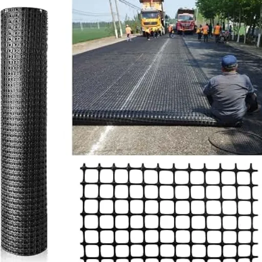
The headline figure is worth stating plainly. Across the test programme, improvements in BCR ranged from 1.5 to 3. Reinforcement can add roughly 50% to 200% more bearing capacity, depending on soil, grid stiffness, and layout.
Settlement improves too. With three or more layers, the same study measured settlement reductions of 50% at a footing pressure of 58 psi. BCR rises with increasing tensile modulus and with decreasing layer spacing.
Now the caveats, which matter more than the headline.
BCR is measured at a settlement
The research evaluates BCR at a specific settlement ratio, s/B, not at zero movement. That is not a technicality. It means the headline number is only reached after the footing has already deflected.
Picture a project engineer, Marcus, reviewing a subgrade improvement claim. The supplier’s literature says “bearing capacity up to 2.4 times.” He checks the arithmetic and it holds.
What the literature does not say is that the 2.4 is reached at a settlement ratio of about 4%. On his 1.2 m footing, that is roughly 48 mm of movement before the full capacity is available. His structure’s serviceability limit is 25 mm. The bearing check passed comfortably. The footing still failed.
That is the trap. A high BCR does not rescue a compressible subgrade.
These are model tests
The values come from small-scale and large-scale model footing tests plus field tests. Scale effects are real, and small-scale tests can overstate gains. The large-scale work is what makes the numbers usable, but the envelope should be treated as design guidance, not a guarantee. If your project carries unusual risk, verify with a site-specific plate load test.
Settlement frequently governs
FHWA GEC 6 states that bearing stresses are typically limited so that total settlements stay on the order of 25 mm (1 in), with differential settlement about half the total. For building footings of 0.5 to 1.0 m width on clay, bearing capacity may indeed control, because small footings fall in the bearing-limited part of the design envelope.
But for larger footings on soft ground, settlement is the check that decides the design. Reinforcement helps both. It just helps them by different amounts, and the settlement gain is the one you can usually rely on.
When Bearing Capacity Is Not the Governing Check
Ask one question before applying anything above. Does this footing fail the bearing check, or the settlement check?
If the unreinforced footing already satisfies bearing capacity at a factor of safety of 3.0, then reinforcement is being specified for settlement, and the design case is different. The geogrid bearing capacity figures in this article are then the wrong tool, and the layout table is only a starting point.
There are also ground conditions where geogrid is simply the wrong answer:
- Highly organic soil or peat. Reinforcement spreads stress. It does not remove compressibility.
- Saturated soil where pumping occurs. The failure is a moisture and drainage problem before it is a reinforcement problem.
- Thick compressible clay where consolidation dominates. Time-dependent settlement is not fixed by a tensile layer.
In those cases the alternatives are over-excavation and replacement, lime or cement stabilisation, wick drains, or piles. Each addresses a different failure mode. Our soft ground guide compares them directly, and our article on geogrid failure modes covers what happens when reinforcement is applied outside its useful range.
Not sure whether your project is a bearing problem or a settlement problem? Send us the subgrade information and footing loads. We will tell you which check governs before you commit to a specification. Contact engineering support.
How to Specify Geogrid for Bearing Capacity
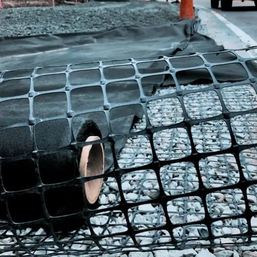
The number that matters for geogrid bearing capacity is tensile modulus at low strain, not ultimate tensile strength.
The LTRC test programme characterised every reinforcement by its tensile strength and its tensile modulus, both at 2% strain. That is the property the analysis uses, because 2% strain is roughly the working range in a reinforced foundation. Most datasheets lead with ultimate strength, because it is the bigger and more impressive number.
Consider a procurement lead, Daniel, comparing two biaxial polypropylene grids. Both are advertised at 30 kN/m ultimate tensile strength. Grid A has a secant modulus of 400 kN/m at 2% strain. Grid B has 250 kN/m.
On paper they look equivalent, and Grid B is cheaper. In a reinforced foundation, Grid A delivers the higher BCR at serviceable settlement. The saving on Grid B is real. So is the capacity he did not get.
What to ask a supplier for
- Tensile modulus
Jat 2% strain, in both machine and cross-machine directions - Aperture size and shape, since interlock depends on the match between aperture and aggregate
- Polymer type, polypropylene or polyester, and junction efficiency
- Whether each value is an index value or a performance value, and the test standard behind it
- Batch test reports, not just a catalogue sheet
Our geogrid specifications reference sets out the test methods behind each of those values, and explains which ones a supplier can legitimately provide.
Quality and supply
Ask for ISO 9001 certification, retained samples, and batch-specific test data. A grid that meets the modulus requirement on a datasheet but varies between batches will produce a foundation that meets the analysis on paper and not in the ground.
Frequently Asked Questions
How much does geogrid increase bearing capacity?
Published footing tests give a bearing capacity ratio of 1.5 to 3, meaning 50% to 200% more ultimate capacity than the unreinforced case. The value depends on soil type, grid tensile modulus, and layer layout. It is measured at a given settlement, not at zero movement.
What is the bearing capacity ratio?
The bearing capacity ratio, or BCR, is the ultimate bearing capacity of a reinforced soil foundation divided by that of the same foundation without reinforcement. A BCR of 2.0 means twice the capacity. It is the standard performance measure for reinforced foundations.
How many layers of geogrid do I need under a footing?
Add layers until you reach the influence depth, about 1.5B below the footing for geogrid in silty clay and about 1.25B in sand. Layers below that depth contribute nothing measurable. In practice, three or more layers is where settlement reduction becomes substantial.
How far below the footing should the first layer go?
0.33B, where B is the footing width. That optimum was measured consistently across sand, silty clay, and crushed limestone. Keeping the top layer within 0.5B also prevents the failure mode that occurs above the reinforcement.
How long should the geogrid layers be?
About 5B, with a usable range of 4B to 6B. Measured strain becomes negligible beyond 2 to 3B from the footing centre, so longer layers add cost without adding capacity.
Does geogrid increase bearing capacity or just reduce settlement?
Both, but by different amounts and at different rates. Bearing capacity gain is mobilised as the footing settles. Settlement reduction is often the more reliable benefit, and on soft ground it is usually the governing check.
Is bearing capacity or settlement the governing check?
For most footings on soft ground, settlement governs. FHWA guidance limits bearing stress so total settlement stays near 25 mm. Check both, but do not assume capacity is the controlling design case.
Conclusion
Geogrid bearing capacity is a quantifiable design property, not a marketing claim. The published range is 1.5 to 3 times the unreinforced ultimate capacity, and the layout that produces it is well established: first layer at 0.33B, spacing at 0.33B, reinforced depth of 1.5B, and layer length of 5B.
Three things decide whether you actually get that gain. The layout has to match those ratios. The grid has to be specified by tensile modulus at 2% strain rather than ultimate strength. And the design has to be checked for settlement, because the BCR figure is mobilised only after the footing moves, and settlement governs more often than capacity.
Get those three right and geogrid bearing capacity becomes a predictable design input. Get them wrong and you have bought a tensile element that is in the wrong place, at the wrong stiffness, solving the wrong problem.
For the wider picture, start with our geogrid soil reinforcement guide, which covers mechanisms, design parameters, and application across the cluster.
Ready to specify? Send us your footing width, subgrade strength, and load case. We will return a recommended layout and the tensile modulus values you need to hold a supplier to. Request a technical quote.