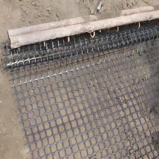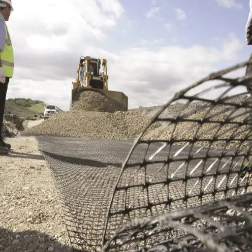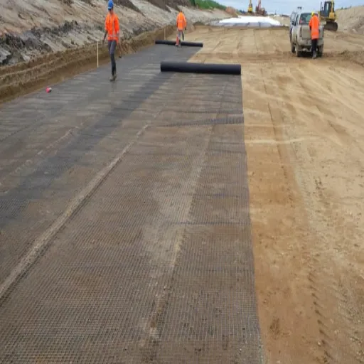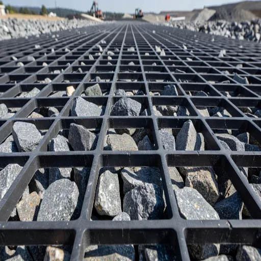
Geogrid pullout resistance is the ultimate tensile load required to slide a geogrid out of the soil along its embedded length. Two mechanisms mobilize it together: interface friction along the rib surfaces, and passive bearing of soil against the faces of the transverse ribs.
That definition matters less than the number it produces. Geogrid pullout resistance sets how long your reinforcement has to be, and length is where reinforced soil structures quietly succeed or fail.
Here’s the problem. Geogrid pullout resistance is the one design parameter that appears on almost no geogrid datasheet and almost no commercial web page. So designers do one of two things. They apply a conservative default that inflates the wall, or they repeat a figure they half-remember from a manual.
This guide gives you the actual numbers: the equation, the verified FHWA defaults, the coefficient of interaction by soil type, a worked anchorage calculation, and the test that replaces every default with real data. For the wider picture, start with our geogrid soil reinforcement guide.
Key Takeaways
- FHWA NHI-10-024 uses F* = 2/3 tan φ for geogrids and geotextiles. The 0.8 that circulates for geogrids is the scale effect factor α, not F*.
- Geogrids beat geotextiles on α (0.8 versus 0.6), worth roughly a third of your embedment length. Not on F*.
- The design parameter is L_e, the length behind the failure surface. It isn’t the total grid length.
- Geogrid pullout resistance mobilizes at 25 to 50 mm of displacement. Ribbed steel needs 12 mm.
- F* and Ci are fill-specific. A supplier quoting one number is quoting one test against one soil.
What Is Geogrid Pullout Resistance?
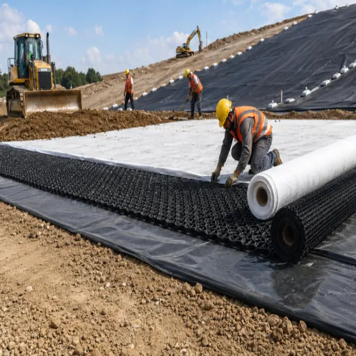
Geogrid pullout resistance is the load at which the grid stops holding and starts sliding. The structure doesn’t necessarily collapse. It deforms, the facing moves, and the reinforced mass stops behaving as a composite. That’s why FHWA checks pullout separately from rupture, with its own resistance factor.
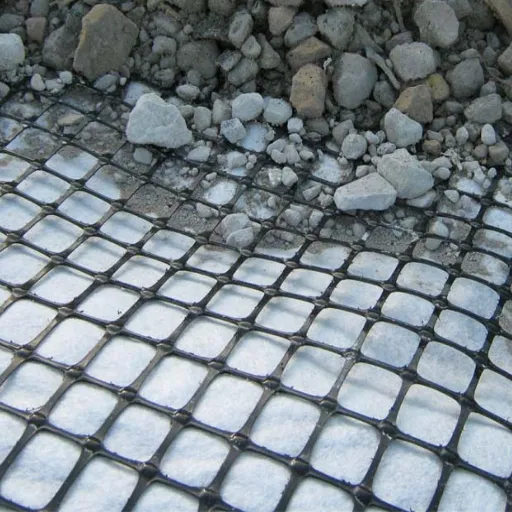
Passive bearing on the transverse ribs is the geogrid’s structural advantage. Soil bears against the rib face much like a small retaining wall. This pullout resistance depends on rib thickness, rib depth, rib spacing, and whether aggregate has locked into the apertures. When it works, it produces resistance that plain friction can’t account for.
Interface friction along the rib surfaces exists in every grid. It’s the weaker path, and it becomes the only path when the aperture is mismatched to the fill or the fill is fine-grained.
FHWA writes that combination as F* = F_q × α_β + tan ρ, where the first term is the passive bearing component and the second is friction. That equation is why the “ribs add resistance plain friction can’t account for” claim holds arithmetically rather than by assertion.
The consequence is often overlooked. Geogrid pullout resistance depends on geometry and fill, not just tensile strength. Two grids with identical strength ratings can still behave very differently in the ground.
The Pullout Equation, Term by Term
FHWA NHI-10-024 gives normalized pullout resistance per unit width as:
P_r = F* × α × σ’_v × L_e × C
| Term | What it means physically | Where the value comes from |
|---|---|---|
| F* | How efficiently this grid mobilizes soil strength | Pullout test, or FHWA default |
| α | Scale effect correction factor: discount for non-uniform stress along an extensible grid | Table 3-6, or tests at multiple lengths |
| σ’_v | Confining stress holding the grid in the soil | Overburden plus surcharge, at that layer |
| L_e | Length of grid behind the failure surface | What you’re solving for |
| C | Surface area geometry. C = 2 for grids, strips and sheets | Constant. Edges are neglected |
The most misread term is L_e. It isn’t the total grid length. It’s the length in the resistant zone, behind the critical failure surface. A 10 m grid crossing a failure surface at mid-length has an L_e of roughly 5 m.
That’s why the failure surface location matters as much as the grid specification. It’s also the most common error in pullout calculations.
Note that C = 2 because both faces of the sheet contribute. The grid is held by soil on both sides along its entire embedded length. If the grid is short, that area is small, and no amount of tensile strength compensates.
For the particle-scale picture of load transfer, see how geogrid works.
The Coefficient of Interaction (Ci)
The coefficient of interaction compares interface shear strength to the shear strength of the soil itself:
Ci = tan δ / tan φ
Here δ is the interface friction angle and φ is the soil friction angle. Ci is nominally a friction ratio, which makes it look as though it must stay below 1.
For geogrids it can exceed 1, because passive bearing on the ribs adds pullout resistance that plain friction can’t explain. A grid measuring Ci above 1 isn’t a testing error. It’s the ribs working.
| Fill type | Typical Ci | Why |
|---|---|---|
| Gravel, crushed angular | about 1.0 | Particles seat in apertures, full passive bearing develops |
| Well-graded sand | about 0.9 | Good interlock, less rib bearing face engaged |
| Silty sand, low-plasticity silt | about 0.8 | Reduced interlock, friction-dominated |
| Clay, cohesive | well below 0.8 | No interlock, suction and moisture dominate, creep risk |
Those are indicative ranges from common design practice, not FHWA table values. Don’t cite them as such.
What is verified, and should carry the design instead, is this. NHI-10-024 Eq. 3-8 gives F* as 2/3 tan φ for geosynthetics absent test data. It caps φ at 34 degrees for MSE select granular backfill unless project testing substantiates more.
Eq. 3-9 gives interface friction as tan ρ = 2/3 tan φ for geotextiles, geogrids and geonets, from direct shear to ASTM D5321.
Because Ci is soil-dependent, the same grid has different geogrid pullout resistance in different fill. That’s why it can’t be a single datasheet number, and why any coefficient of interaction a supplier quotes is valid only for the fill they tested.
F* and α: The Pullout Resistance Factor, Decoded
Design notes, software defaults and supplier literature quote two different things. One says the pullout resistance factor for a geogrid is 0.8 tan φ. The other says it’s 2/3 tan φ for all geosynthetics. Both are in circulation, and engineers routinely can’t reconcile them.
They aren’t competing opinions. They come from different manual editions, and they assign the 0.8 to different terms.
The current convention
FHWA NHI-10-024, published 2009:
| Parameter | Geogrid | Geotextile | Steel, inextensible |
|---|---|---|---|
| F* absent testing | 2/3 tan φ (Eq. 3-8) | 2/3 tan φ (Eq. 3-8) | tan ρ = 1.2 + log C_u at top, 2.0 max |
| α (Table 3-6) | 0.8 | 0.6 | 1.0 |
| F* × α at φ = 34° | about 0.36 | about 0.27 | about 1.80 at top of wall |
Read the first row again. Geogrids and geotextiles share the same F* default. The manual doesn’t give geogrids a higher pullout resistance factor.
The predecessor convention
FHWA-RD-89-043 works its design example as F* = Ci × tan φ = (0.8)(tan 34°) = 0.54, with α = 2/3 in the same equation.
So the older generation put 0.8 on the interaction coefficient and two-thirds on the scale effect. The current generation reverses that.
Why the error survived
| F* | α | F* × α at φ = 34° | |
|---|---|---|---|
| Current (NHI-10-024) | 2/3 tan φ = 0.450 | 0.8 | about 0.36 |
| Predecessor (RD-89-043) | 0.8 tan φ = 0.540 | 2/3 | about 0.36 |
The product is the same. That’s why the two conventions have been quietly interchangeable for decades, and why nobody caught the swap. The number entering your equation is nearly identical. Only the attribution is wrong.
The rule is simple. Pick the convention your governing code uses and apply it consistently. Never take F* from one manual and α from another, or your embedment length will be wrong by about a third.
There’s a useful point buried here. The reason a geogrid outperforms a geotextile is α, not F*. Alpha discounts non-uniform stress transfer along an extensible reinforcement. A stiff grid distributes load more evenly, so it’s discounted less.
One more cap worth remembering. NHI-10-024 caps the design friction angle at 34 degrees for select granular backfill unless project testing supports more. Using a 38 degree laboratory value without justification is a common and expensive mistake.
How Geogrid Pullout Resistance Is Tested
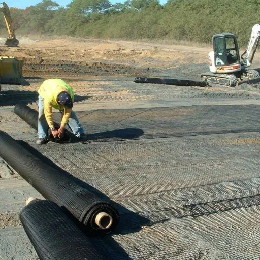
ASTM D6706 embeds a grid specimen in a soil-filled box, confines it under controlled normal stress, and pulls it out at constant displacement rate while load and displacement are recorded. That test is how geogrid pullout resistance moves from a default to a measured value. FHWA adopts the procedure by reference.
Four things decide whether a result is usable for design.
- Embedded length of at least 600 mm (24 in.). Shorter specimens overstate pullout resistance.
- The actual project fill. F* and Ci are fill-specific. A test in someone else’s gravel tells you nothing about your silt.
- The actual confining stresses across the range of reinforcement layers.
- A stated reading criterion. FHWA takes the greater of the peak value before, or the value at, 20 mm displacement at the front for inextensible reinforcement, or 15 mm at the embedded end for extensible reinforcement.
The limitation deserves stating plainly. D6706 produces a short-term capacity. It doesn’t capture soil or reinforcement creep, which FHWA flags as significant in fine-grained fills. Where silt or clay is used, long-term testing is a separate exercise and should be required.
Three adjacent tests are worth knowing by name. ASTM D5321 covers soil-geosynthetic direct shear for interface friction, which governs sliding rather than pullout. ASTM D7737 measures individual geogrid junction strength, the rib-to-rib connection carrying passive bearing load. ASTM D6637 covers single-rib tensile strength.
Designing Geogrid Anchorage Length: A Worked Calculation
Geogrid pullout resistance must resist the factored tensile force at that layer. In allowable stress terms, the factor of safety is 1.5 for granular fill. Under LRFD, the pullout resistance factor is 0.90 for static loading, rising to 1.20 for combined static and earthquake loading.
Rearranged for length:
L_e = T_max × FS / (F* × α × σ’_v × C)
A layer sits 4 m deep in granular fill at 19 kN/m³ with φ = 34 degrees. The internal stability analysis gives T_max = 28 kN/m.
- Confining stress. σ’_v = 19 × 4 = 76 kPa
- F*. 2/3 × tan 34° = 0.667 × 0.675 = 0.450
- α. Geogrid default = 0.80
- C. 2 for a grid
- Solve. L_e = (28 × 1.5) / (0.450 × 0.80 × 76 × 2) = 42 / 54.7 = 0.77 m
- Total length and the 0.7H check. Add 2.3 m from face to failure surface = about 3.1 m. Now check the 0.7H minimum.
The sensitivity that teaches the lesson
Repeat Step 5 with α = 0.6, the geotextile default. L_e rises to about 1.02 m, a third longer. That’s the geogrid advantage in metres of material and excavation, not in adjectives.
Then repeat with φ = 30 degrees instead of 34. L_e climbs to about 0.90 m. You now know which two inputs to argue about in the design review.
Check against the minimum
FHWA recommends a minimum reinforcement length of 0.7H, with a practical minimum of 8 ft (2.5 m). Sloping backfill pushes that to 0.8H, seismic to 0.8H through 1.1H.
Pullout governs in tall walls and poor fill. The geometric minimum governs in short walls. Readers are often surprised that the calculation doesn’t control on their project. Check both, and report both.
For seismic design, FHWA reduces F* to 80 percent of its static value unless dynamic pullout tests are performed. That provision is easy to miss and it isn’t optional.
To see where this check sits among rupture, sliding, bearing and global stability, work through the reinforced soil design sequence.
What Happens When Geogrid Pullout Resistance Is Under-Designed
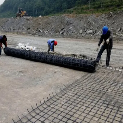
The signature of a pullout failure is displacement, not rupture. The grid doesn’t break. It slides. You see facing movement, settlement behind the facing, or a bulge, often months after construction and under first full service load.
When geogrid pullout resistance is under-designed, the cause is usually one of three things.
L_e too short is the most common by a wide margin, usually because the grid was specified by total length without checking where the failure surface sits. Wrong fill collapses Ci when a cohesive or rounded material is used against a granular design assumption. Aperture mismatch prevents passive bearing from developing at all; our guide to geogrid aperture size covers the sizing rules.
What makes this insidious is that the same grid, correctly embedded in gravel, passes. In silt, the same length fails. The specification looked identical on paper.
| Reinforcement | Displacement to mobilize pullout |
|---|---|
| Smooth steel strip | 1.2 mm |
| Ribbed steel strip | 12 mm |
| Geogrid, extensible grid | 25 to 50 mm |
| Geotextile, extensible sheet | 25 to 100 mm |
Over an abutment, a culvert, or any structure that can’t tolerate much movement, a geogrid mobilizes pullout at two to four times the displacement of ribbed steel. That may still be the right choice, but it has to be a decision rather than a surprise. The geogrid versus steel reinforcement comparison works through that trade.
What to Ask a Supplier
Most geogrid datasheets quote tensile strength, aperture, and sometimes junction efficiency. Very few quote F* or Ci, because those require D6706 testing against a specific fill, which no manufacturer can do for every customer’s soil.
A default F* isn’t a product property. It’s a fallback. Any supplier presenting one as a product specification is either confused or hoping you are.
Four questions separate a technical supplier from a catalogue. Do you have D6706 pullout data for this product, and in what fill? What are the rib thickness and rib spacing? What’s the junction efficiency to ASTM D7737? And which design convention do your published F* and α values use?
If the answer to the first is no data, use the conservative defaults, accept the longer embedment, and consider project-specific D6706 testing when the fill is anything other than select granular. On a large wall, testing cost is routinely less than the extra grid and excavation it saves.
Need to check an anchorage calculation against your fill? Our engineering team can work through the pullout check with you and quote geogrid on a MARV basis with rib geometry and junction efficiency stated. Contact engineering support.
Frequently Asked Questions
What is the coefficient of interaction for geogrid?
Ci compares interface shear strength to soil shear strength, as tan δ divided by tan φ. For geogrids in granular fill it typically runs around 0.9 to 1.0, and can exceed 1 because rib bearing adds pullout resistance. It falls sharply in silt and clay.
What is the pullout resistance factor F* for geogrid?
FHWA NHI-10-024 uses 2/3 tan φ for geosynthetics absent test data, with φ capped at 34 degrees. Older guidance used Ci tan φ with Ci near 0.8. Both remain in circulation, and they put the 0.8 on different terms.
How long should geogrid be embedded behind the failure surface?
Solve L_e = T_max × FS / (F* × α × σ’_v × C). For granular fill at 4 m depth carrying 28 kN/m, that gives about 0.77 m at a factor of safety of 1.5. Then check the 0.7H minimum as well.
What factor of safety applies to pullout?
Allowable stress design uses 1.5 for granular fill. Under LRFD, the pullout resistance factor is 0.90 for static loading and 1.20 for combined static and earthquake loading.
How is geogrid pullout resistance tested?
ASTM D6706 embeds the grid in a confined soil box and pulls it at constant displacement rate. FHWA requires a minimum 600 mm embedded length for design-grade results, read at 15 mm displacement at the embedded end for extensible reinforcement.
Does geogrid have higher pullout resistance than geotextile?
Yes, but not because F* is higher. Both share the same default of 2/3 tan φ. Geogrids get a better scale effect factor, 0.8 against 0.6, because a stiffer grid transfers stress more evenly along its length.
Conclusion
Geogrid pullout resistance sets reinforcement length, and it’s the one number most datasheets leave out. Four points carry the design.
L_e is measured behind the failure surface, not from the face. Get that wrong and the calculation is meaningless however careful the rest of it is.
F* and α are different numbers. In current FHWA guidance the 0.8 belongs to α, and F* is 2/3 tan φ for geogrids and geotextiles alike. The geogrid advantage over geotextile is α, worth roughly a third of your embedment length.
Defaults are fallbacks rather than product properties. D6706 testing on the project fill replaces them, and on a large wall it usually pays for itself.
Finally, geogrid pullout resistance mobilizes at 25 to 50 mm of displacement. Over a settlement-sensitive structure, plan for that rather than discovering it.
If you’re sizing reinforcement for a wall or slope and want the anchorage check verified against your actual fill, request a technical quote and our engineers will work through it with you. Export orders ship with test reports, and datasheet values are quoted on a MARV basis so the numbers you design to are the numbers you receive.