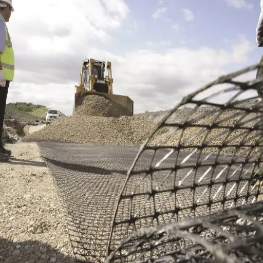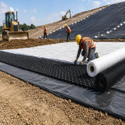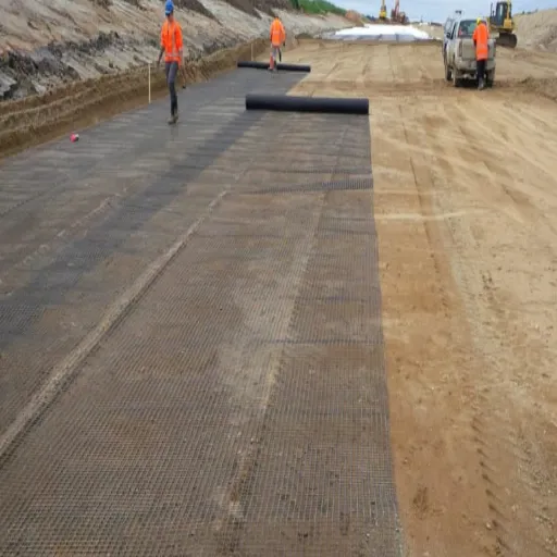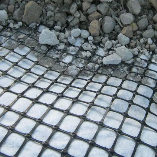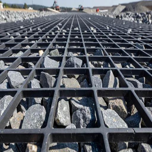
The eight geogrid failure modes are water, marginal backfill, global instability, pullout, connection failure, installation damage, tensile rupture, and UV degradation. They are not equally likely, and that is the part most guides leave out.
The Geosynthetic Institute has catalogued 320 failed geogrid and geotextile reinforced MSE walls. In 64% of them, water was the cause. In 72%, the backfill was fine grained silt or clay. In most of those structures, the reinforcement was still doing its job when the wall came down.
If you’re specifying or inspecting a reinforced soil structure, you already know the grid has to be strong enough. What you may not have is a way to rank the threats. That ranking is what this article gives you: eight modes, ordered by how often they appear in the forensic record, each paired with the check that prevents it.
It draws on FHWA design guidance, the GSI failure database, and two peer reviewed case history papers. For the full design context behind these checks, see our guide to geogrid soil reinforcement.
Key Takeaways
- In GSI’s database of 320 failed reinforced MSE walls, 64% failed due to water and 72% used fine grained silt or clay backfill.
- Geogrid failure modes split into two groups: the grid fails (rupture, pullout, connection, installation damage, UV) and the structure fails with the grid intact (drainage, global instability, facing).
- FHWA sets a hard ceiling of RF_ID = 1.7 for installation damage. Above that, roughly 40% strength loss, the geogrid and backfill combination should not be used.
- Reinforcement length of 0.7H instead of 0.5H cuts deformation by about 50%. Deformation is bought with length, not strength.
- The AASHTO Simplified Method over predicts measured reinforcement loads by roughly a factor of two, with a coefficient of variation of 91%.
What Is a Geogrid Failure Mode?
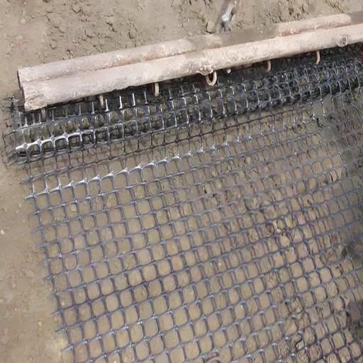
A geogrid failure mode is a specific mechanism by which a reinforced soil structure stops performing its design function. It covers two different things: the geogrid losing tensile capacity, and the structure failing while the geogrid remains intact.
Put another way, reinforced soil failure modes divide into the ones a material datasheet can address and the ones it cannot. Most guides cover only the first group.
That distinction has commercial consequences. A supplier asked to warrant against “geogrid failure” is warranting the first category. The second is a design, drainage, and construction problem that no material specification prevents.
When a wall bulges after heavy rain, the grid did not fail. The drainage did. When a slope slides along an interface beneath the reinforced zone, the grid was bypassed, not broken.
The Eight Geogrid Failure Modes Ranked
Here are the modes, with the field signature that identifies each and how much weight the evidence gives it.
| Mode | Category | Field signature | Evidence weight |
|---|---|---|---|
| 1. Water and drainage | Structural | Bulging, seepage at the face, movement after rain | Dominant: 64% of 320 failures |
| 2. Marginal backfill | Structural | Progressive settlement, rising pore pressure | Dominant: 72% of 320 failures |
| 3. Global and compound instability | Structural | Slip surface passing behind or under the reinforced zone | Common |
| 4. Pullout and anchorage | Material | Face moves, grid unbroken | Common |
| 5. Connection and junction | Material | Facing panels displace, grid body intact behind the joint | Common in MSE walls |
| 6. Installation damage | Material | Random rib and junction damage, no visible external sign | Routine, quantified by RF_ID |
| 7. Tensile rupture and creep | Material | Localised necking, break, excessive strain | Rare when designed to LTDS |
| 8. UV and chemical degradation | Material | Surface embrittlement on exposed wrap around faces | Rare when buried |
The gap between ranks one and two and everything below them is not close. Modes 3 through 8 are the ones design codes check explicitly. Modes 1 and 2 are the ones codes assume you have handled. The reinforced soil design framework covers those checks in full.
Modes 4 and 6 both begin with interlock, which starts with geogrid aperture size matched to the aggregate. Get that wrong and the grid slides through the fill before any other check matters.
Material Failure Modes: Rupture, Pullout and Connection
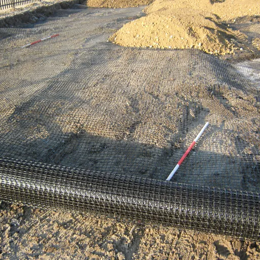
Tensile rupture: the mode everyone designs for and rarely gets
Design strength is not ultimate strength. FHWA computes allowable tension as the ultimate value divided by the product of installation damage, creep, and durability reduction factors. Rupture is rare precisely because those factors are conservative. When it does happen, the cause is usually upstream of the calculation: ultimate strength read from a datasheet at the wrong strain, or a product that was not the product specified.
Pullout: the mode that looks like rupture but is not
The field signature separates them cleanly. In pullout, the facing moves and the grid is unbroken. The anchorage length beyond the potential failure surface was too short to develop the load. An inspector who finds a displaced face and a torn grid should check where the tear sits. Mid-panel tears point to rupture; clean pulls point to anchorage.
FHWA sets minimum reinforcement lengths of 0.7H for static loading, 0.8H for sloping backfill surcharge, and 0.8 to 1.1H under seismic loading. These are floors, not targets. The mechanics are covered in our guide to geogrid pullout resistance.
Connection and junction failure: the weak point that is not the grid
FHWA requires the connection to be designed for the maximum reinforcement tension, and states that connection strength is specific to each facing unit and reinforcement combination. It has to be developed by test for that pairing.
There is a specification trap here that rarely appears in supplier literature. Polyester geogrids and geotextiles should not be cast into concrete for connections, because of potential chemical degradation. If your facing detail assumes an embedded polyester grid, it is wrong before the wall is built.
Installation and Environmental Failure Modes
Geogrid installation damage: the only mode with a published price list
Geogrid installation damage is the strength lost to abrasion, puncturing, and notching during fill placement and compaction. ASTM D5818 field trials measure it, and FHWA publishes the ranges.
| Geosynthetic | Type 1 backfill (max 100 mm) | Type 2 backfill (max 20 mm) |
|---|---|---|
| HDPE uniaxial geogrid | 1.20 to 1.45 | 1.10 to 1.20 |
| PP biaxial geogrid | 1.20 to 1.45 | 1.10 to 1.20 |
| PVC coated PET geogrid | 1.30 to 1.85 | 1.10 to 1.30 |
| Acrylic coated PET geogrid | 1.30 to 2.05 | 1.20 to 1.40 |
| Woven geotextiles | 1.40 to 2.20 | 1.10 to 1.40 |
| Non woven geotextiles | 1.40 to 2.50 | 1.10 to 1.40 |
| Slit film woven PP geotextile | 1.60 to 3.00 | 1.10 to 2.00 |
Read the two columns against each other. Backfill choice moves the factor more than polymer choice does. A PVC coated PET grid in coarse angular rock carries a factor up to 1.85, while the same grid in fine backfill sits at 1.30.
FHWA also sets a hard limit. A geogrid and backfill combination should not produce an RF_ID above 1.7. Above that, roughly a 40% strength loss, the remaining strength becomes highly variable and unreliable for design, and FHWA states the combination should not be used. This is a pass or fail criterion, not a number to absorb into the calculation.
Two field rules prevent it. Keep at least 6 in. (150 mm) of backfill between the reinforcement and compaction or spreading equipment. Use lightweight compaction equipment and thinner lifts within 3 ft (1 m) of the facing.
Both are inspectable, and both are routinely violated. Our geogrid installation guide walks through the sequence.
UV and chemical degradation: a real risk in a narrow window
Most geogrid is buried, so UV is a construction phase problem rather than a service life one. FHWA states that geosynthetic facing elements should not be left exposed to sunlight for permanent walls. The risk concentrates in wrap around and vegetated faces, and on sites where backfill placement lags delivery by weeks.
The testable criterion is ASTM D4355: 70% strength retained after 500 hours for polypropylene and polyethylene, 50% for polyester. The default durability reduction factor is only available if that criterion is met.
Structural Failure Modes With an Intact Grid
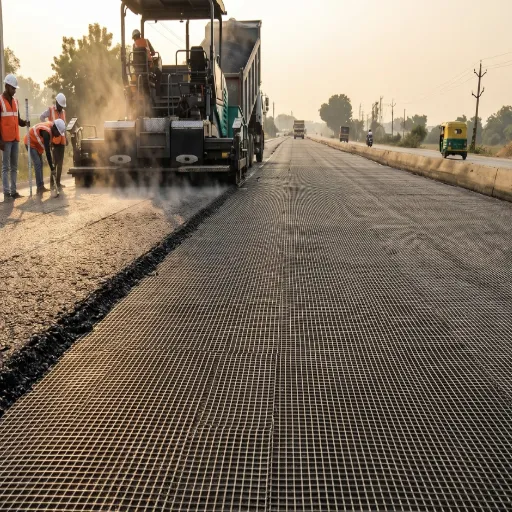
This is where the forensic record points, and it is the section most guides skip.
Water: 64% of the database
The GSI finding is worth quoting in full: “Within GSI’s database of 320 failed mechanically stabilized earth (MSE) walls reinforced with geogrids or geotextiles, 64% have failed due to water. Furthermore, 72% have been constructed with fine grained silt and/or clay soils. Taken together, these low permeability backfill soils do not drain easily and instead build up hydrostatic pressure leading to the large number of failures.” (GSI webinar W-2)
The mechanism is straightforward. Soils with less than 3 to 5% non plastic fines are free draining. Above that threshold, permeability drops sharply and drainage has to be designed explicitly. FHWA flags instability risk when fill permeability falls to about 0.002 cm/sec.
This is the most consequential geogrid failure mode, and the cheapest to prevent. A drainage layer and a graded surface cost a fraction of a heavier grid, and unlike the grid, they address the mechanism that actually brings walls down.
The trap that catches contractors is subtler. FHWA notes that granular fill containing even a few percent fines, which can develop or increase through breakdown during compaction, may not be free draining. A spec compliant crushed stone can lose its drainage capacity through handling alone.
There is a construction phase failure too. FHWA requires the fill surface to be graded away from the face at the end of each working day, because ponding behind a partially built wall saturates the fill and can move the structure before it is finished.
Global and compound instability: the check that gets delegated
A compound failure surface passes behind or under the reinforced zone and then through part of it. FHWA requires this check when there are changes in reinforced soil type or reinforcement length, high surcharge loads, seismic loading, sloping faces, significant slopes at the toe or above the wall, or tiered construction.
Here is the commercial trap worth naming. FHWA observes that MSE wall vendors typically exclude the overall stability check and its responsibility from their package unless the contract documents require it. The party supplying the grid is often not the party checking global stability. On a design build package, it is worth confirming that somebody is.
The foundation is part of that check. Where the structure sits on weak ground, the governing question shifts from reinforcement to geogrid bearing capacity on the subgrade beneath the reinforced mass.
Facing and deformation
Lateral displacement depends on fill placement, compaction, reinforcement extensibility and length, connection details, and facing type. Not on grid strength alone.
The most useful number here is FHWA’s finding that raising the length to height ratio from the theoretical lower limit of 0.5H to the specified 0.7H decreases deformation by about 50%. If a wall is moving, the first question is length, not strength.
Case Forensics: Geogrid Wall Failure at Yeager Airport
A 73 m (240 ft) reinforced soil slope supported Runway 5 at Yeager Airport in Charleston, West Virginia. It failed catastrophically on 12 March 2015, after about eight years in service.
The post failure investigation found a fill to rock interface of degraded sedimentary rock beneath the reinforced slope. Shear strength testing covered the coarse fill and the fully softened and residual strengths of fine grained soil from the interface. Limit equilibrium analysis explained the failure by accounting for changes in shear strength within the sedimentary rock.
There was a geometric complication. Because the slope had an outside radius, the uniaxial geogrid ran at varying angles to the direction of sliding, from parallel to almost perpendicular. The analysis had to be three dimensional to capture that.
The lesson is not that reinforcement failed. The design checked the reinforced mass, and the failure surface found a weaker path beneath it. That is mode 3 in the table, and it is invisible to any check that treats the reinforced zone as a closed system.
It is also the hardest geogrid failure mode to see coming. Water leaves a stain. A missing drainage outlet is a drawing error you can catch on site. An interface of degraded rock beneath a finished slope leaves no surface evidence until it moves.
The Over-Design Failure Mode Nobody Counts
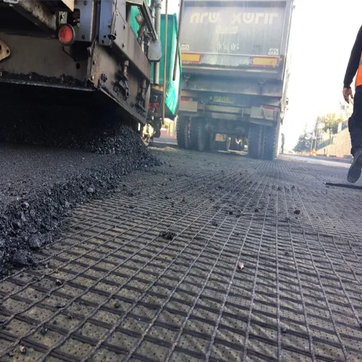
There is a ninth mode, and it never appears in a failure database because nothing collapses. It is spending money on the wrong variable.
Allen and colleagues compared measured reinforcement loads against predicted loads across 11 full scale geosynthetic walls. The AASHTO Simplified Method produced an average measured to predicted bias of 0.45, with a coefficient of variation of 91%. The conventional method predicted roughly 2.2 times the load actually measured, with enormous scatter. Their proposed method produced a bias of 0.99 and a variation of 36%.
Over design isn’t free. It buys heavier grids, longer panels, larger connections, and more imported fill. None of that improves the two modes responsible for 64% of documented failures. A project that spends its budget on grid strength instead of drainage has optimised the wrong variable.
To be clear, over design isn’t a safety failure. The claim is about where attention and money go, not about risk.
How to Prevent Geogrid Failure
Eight checks, each mapped to the mode it prevents.
- Test placed fill gradation, including fines after compaction. Prevents modes 1 and 2. Require under 3 to 5% non plastic fines for free draining classification. If exceeded, design drainage explicitly.
- Specify and inspect the back drainage zone and its outlet. Prevents mode 1. The outlet is the component that gets forgotten.
- Require global and compound stability analysis in the contract documents. Prevents mode 3. Do not assume the wall vendor is doing it.
- Verify anchorage length against 0.7H static, 0.8H sloping, 0.8 to 1.1H seismic. Prevents mode 4.
- Require connection test data for the specific unit and reinforcement pairing, with 90% or better junction efficiency. Prevents mode 5.
- Enforce 6 in. of cover before equipment, and lightweight compaction within 3 ft of the face. Prevents mode 6. Reject any RF_ID above 1.7.
- Specify long term design strength, not ultimate strength, and require the reduction factors used. Prevents mode 7.
- Require ASTM D4355 UV data if any geogrid will be exposed more than a few weeks. Prevents mode 8.
If you are checking an existing wall, start with the drainage outlet and the fill source records. Those two items explain most of what goes wrong.
Want the specification checked before you order? Request a technical quote with your wall height, backfill gradation, and design life, and we will return the RF_ID and long term strength basis in writing.
Frequently Asked Questions
What are the most common geogrid failure modes and MSE wall failure causes?
Water and marginal backfill dominate both. GSI’s database of 320 failed reinforced MSE walls attributes 64% to water and records 72% built with fine grained silt or clay backfill. Poor compaction and an unassigned global stability check cover most of the remainder.
Can a geogrid wall fail without the geogrid breaking?
Yes, and it is the normal case. Global and compound instability, drainage failure, and facing movement can all bring down a structure while the grid remains unbroken. The Yeager Airport geogrid wall failure ran along an interface beneath the reinforced zone.
What is geogrid pullout failure?
Pullout is the grid sliding out of the stable soil mass instead of carrying tension. The facing moves while the grid stays unbroken. It usually means the anchorage length beyond the potential failure surface was shorter than the minimum, commonly 0.7H for static loading.
How much strength does geogrid lose during installation?
Between about 9% and 67%, depending on polymer and backfill. FHWA’s RF_ID values run from 1.10 for geogrids in fine backfill up to 3.00 for slit film woven polypropylene in coarse angular rock. Any combination above 1.7, roughly a 40% loss, should not be used at all.
How long can geogrid be exposed to sunlight?
FHWA advises against leaving geosynthetic facing exposed on permanent walls at all. Where exposure is unavoidable, require ASTM D4355 data showing at least 70% strength retained after 500 hours for polypropylene and polyethylene, or 50% for polyester.
How do I check an existing geogrid wall for distress?
Look for face bulging, seepage or damp patches at the face, settlement of the crest, and movement that appears or worsens after rain. Rain triggered movement points to drainage. Progressive movement without rain points to global stability or anchorage.
Conclusion
Geogrid failure modes are usually described as a list of things that can go wrong with the grid. The forensic record says the grid is rarely the variable that matters.
Water caused 64% of the 320 documented failures in GSI’s database. Fine grained backfill was present in 72%. Both are drainage and specification problems, and neither is fixed by buying a stronger geogrid. The material modes are real, but design codes already check them, and FHWA gives you the numbers to verify each one.
The practical sequence is short. Test the placed fill. Inspect the drainage outlet. Confirm that someone owns the global stability check. Then specify strength with the reduction factors stated in writing.