Geogrid seismic design is the process of checking a geogrid-reinforced wall, slope, or embankment against earthquake loading. It uses pseudo-static or dynamic analysis to verify external stability, internal stability, pullout, connections, and allowable displacement, so the structure can deform without losing its load path.
An earthquake doesn’t usually ask the geogrid to be stronger. It asks the wall to move, crack, settle, and still keep soil and reinforcement working together.
In the 1994 Northridge earthquake, two geosynthetic-reinforced segmental walls in Los Angeles developed tension cracks in the backfill. Pseudo-static analyses of those walls were consistent with the observed cracking (Bathurst and Cai, 1995). That is the useful kind of performance record. Not “it survived,” but “we can predict how it moved.”
Most geogrid content treats seismic design as a horizontal force added to a static calculation. The actual procedure changes the load path, the material rules, and the acceptance criterion. This guide covers the four numbers that change, the checks that govern, and what to specify. For the underlying mechanics, see our guide to geogrid soil reinforcement.
Key Takeaways
- Seismic design is displacement-based. FHWA typically accepts 50–100 mm (2–4 in) of lateral movement if the structure can tolerate it.
- Creep is excluded from the dynamic seismic component because earthquake loading is transient. The static component still includes creep.
- Pullout resistance is reduced to 80% of its static value, and friction-dependent connection strength is also reduced to 80%.
- Water, foundation soil, and connections decide performance more often than the tensile strength of the grid.
- MSE walls are checked where the acceleration coefficient exceeds 0.05; reinforced slopes are checked at any acceleration.
What Is Geogrid Seismic Design?
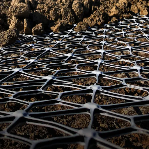
Geogrid seismic design is the earthquake check for a reinforced soil structure. It asks whether the reinforced mass can sustain the combined static and seismic loads, and whether the resulting movement is tolerable.
There are two analysis families. Pseudo-static analysis applies a constant horizontal acceleration to the mass. It uses Mononobe-Okabe for earth pressure, or a generalized limit-equilibrium slope stability analysis for complex geometry.
Dynamic analysis uses time-history records with finite element or finite difference models. It is used for tall walls, soft ground, complex geometry, and critical structures.
A 2025 review of MSE wall design in seismic regions describes the choice plainly. Reinforced soil walls perform relatively well under seismic action because of their flexibility, and the method depends on the complexity of the site (Korini, 2025).
The code basis in the United States is AASHTO LRFD Extreme Event I, implemented in FHWA NHI-10-024 Chapter 7. The external stability check is displacement-based, not a conventional factor of safety.
Why Reinforced Soil Performs Well, and Where the Record Ends
Reinforced soil has a genuine seismic advantage. The mass behaves as a composite block: flexible, ductile, with no tensile weak plane. FHWA states that MSE wall and slope structures are “quite resistant to dynamic forces developed during a seismic event” because of their flexibility.
Japan provides the strongest long-term record. More than 135 km of geosynthetic-reinforced soil retaining walls with full-height rigid facings have been built, including high-speed rail lines. A number performed very well in the 1995 Kobe and 2011 Great East Japan earthquakes (Tatsuoka, Tateyama and Koda, 2013).
That record belongs to walls with a competent foundation, positive drainage, a sound connection, and compacted, graded backfill. Remove one and the record does not transfer.
The record shows the system can work. It doesn’t show which detail will govern your wall. That is what the design checks are for.
If your project has seismic demand and you need the material data behind these checks, request a technical quote and our engineering team will review the specification with you.
The Seismic Load Path: Four Numbers That Change
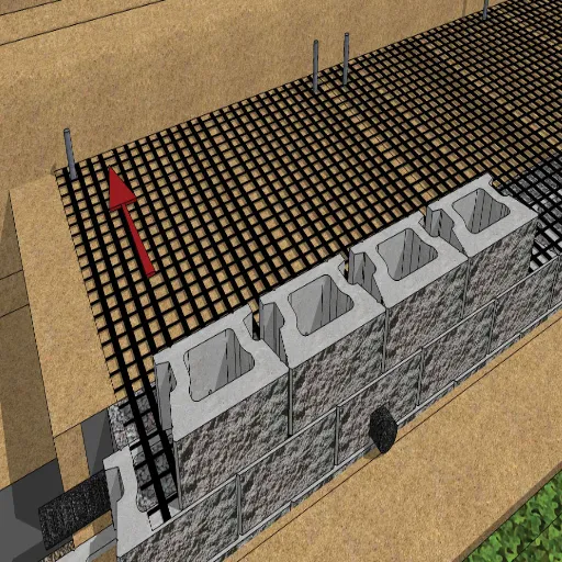
Seismic design changes four numbers. These drive the calculation.
1. The hazard number: kmax and kav. Establish peak ground acceleration (PGA) and spectral acceleration at one second (S1). Determine the site class and site factors. Then compute kmax as the site factor times PGA.
The acceleration used in the analysis is not kmax. FHWA applies a wall-height-dependent reduction to get kav, the average acceleration within the reinforced zone. For walls under about 20 ft (6 m) on firm ground, kav is close to kmax. Taller walls get a lower average.
Two triggers matter. MSE walls are checked where the acceleration coefficient exceeds 0.05. Reinforced soil slopes are checked regardless of acceleration magnitude. Where ground acceleration exceeds 0.29g, FHWA recommends a deformation analysis.
2. The thrust number: PAE. Dynamic active earth pressure is computed from Mononobe-Okabe as PAE = 0.5 KAE γ h². Mononobe-Okabe assumes homogeneous, cohesionless backfill and simple geometry. For c-φ soils, broken slopes, or complex surcharges, use a generalized limit-equilibrium analysis instead.
3. The inertial number: PIR. The reinforced mass itself is shaken. FHWA uses PIR = 0.5 kav W, where W is the weight of the reinforced mass and any permanent overlying loads.
The 0.5 factor assumes half the mass contributes. A 2014 Colorado DOT study argued that the full mass should be used and recommended deformation-based finite element analysis for connections and wall ends. This remains an open debate.
4. The reinforcement increment: Tmd. The internal inertial force is Pi = kav Wa, where Wa is the weight of the active zone. It is distributed across the reinforcement layers as Tmd = Pi / n. The total factored load per layer is Ttotal = Tmax + Tmd.
The seismic case adds load, but it also changes the rules for how that load is resisted. That is where most of the design consequence sits.
External Stability: Designing for Tolerable Movement
The external check follows a sequence. Compute PAE and PIR. Check the sliding capacity-to-demand ratio. If it is below one, find the yield coefficient ky where sliding begins.
Then compute displacement from ky/kmax, kmax, and peak ground velocity, and compare it with the tolerable limit.
FHWA describes typical practice as limiting lateral displacement to 2–4 in (50–100 mm), assuming structures at the top or toe can tolerate it. The limit is project-specific, not universal.
The load resultant must stay within the middle two-thirds of the base for the static case, and the middle eight-tenths for the seismic case. Bearing resistance uses a resistance factor of 1.0 for the extreme event.
Here is the part that surprises engineers trained on static factors of safety. Zero movement is not the acceptance criterion. A wall designed to not move at all under the design earthquake is likely over-conservative. A wall designed to move 60 mm and keep its load path is doing what the code intends.
Consider a project engineer we will call Daniel. He sized a 9 m geogrid wall for a site with a design PGA of 0.25g. His first pass added the seismic force, then increased reinforcement until the static factor of safety returned to 1.5. The wall needed two extra layers and a longer grid.
His reviewer ran the displacement check: the wall moved about 40 mm, inside the 50–100 mm tolerance. The extra layers were not required by the code. They were required by a static habit. Daniel kept one for constructability and removed the other.
Ling, Leshchinsky and Perry (1997) showed that the reinforcement length required to resist direct sliding rises rapidly with acceleration and can become impractical. Their alternative was to design for a tolerable displacement against direct sliding. That is the basis for the check FHWA now uses.
Internal Stability in Geogrid Seismic Design: Rupture, Pullout, and the Creep Exemption
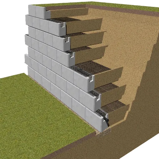
Internal stability is where the material rules change. The total load per layer is Ttotal = Tmax + Tmd. The static and dynamic components are designed separately.
For tensile rupture, the static component uses the full reduction-factor stack, including creep. The dynamic component uses installation damage and durability reductions, but not creep. FHWA’s reasoning is direct: creep requires long-term sustained load, and seismic loading is transient.
The required ultimate strength is the sum of the two components, Tult = Srs + Srt. The resistance factor for combined static and earthquake loading is 1.20.
This provision has a commercial consequence. A geogrid’s long-term design strength is much lower than its ultimate strength because of creep.
Removing creep from the seismic increment lets the same product carry a larger short-term load than a naive calculation suggests. Applying every factor to the increment over-designs. Ignoring pullout and connection under-designs.
For pullout, FHWA reduces the pullout resistance factor F* to 80% of its static value, unless dynamic pullout tests are performed.
For connections, the factored long-term connection strength must exceed Ttotal. Where the connection depends partially or fully on friction between facing blocks and reinforcement, the connection strength for seismic design is reduced to 80% of its static value. Mechanical connections that do not rely on friction do not get the 0.8 multiplier.
Facing detailing follows the same logic. Blocks above the uppermost layer must be checked for toppling. Where seismic analysis is required, modular-block walls should use shear keys or pins and shouldn’t rely fully on friction.
Reinforcement length has three separate rules. The minimum is the greater of 0.7H or 8 ft (2.5 m). Sloping surcharge fills or concentrated loads such as abutments typically require 0.8H to 1.1H. Where seismic loading could cause tension cracks behind the reinforced zone, extend the upper two layers by 3 ft (0.9 m).
| Check | What it verifies | FHWA seismic provision | Specification consequence |
|---|---|---|---|
| External sliding | Displacement under dynamic thrust | ky and displacement equations; 50–100 mm limit | Agree the tolerable movement with the structure above or below |
| Bearing and eccentricity | Foundation pressure and load resultant | Middle 8/10 at EQ = 1.0; resistance factor 1.0 | Foundation improvement may control |
| Tensile rupture | Reinforcement strength | Static and dynamic split; no creep on dynamic; resistance factor 1.20 | Do not apply creep reduction to the seismic increment |
| Pullout | Anchorage length | F* × 0.8 unless dynamic pullout tests | Longer anchorage or higher-friction fill |
| Connection | Facing-to-reinforcement load transfer | 0.8 × static for friction-dependent connections; shear keys or pins | Connection test data, not just grid strength |
| Facing | Toppling above the top layer | Check blocks above the uppermost layer | Detailing, not material |
The reinforced soil design framework covers the static checks that these seismic provisions modify. Seismic design is an additional case, not a replacement.
Where Seismic Walls Actually Fail: Water, Foundation, Connection
The grid is rarely the weak link. The code’s seismic adjustments concentrate on pullout and connections, not on adding tensile strength. That is a strong hint about where the risk sits.
Water is the amplifier. High groundwater generates excess pore-water pressure during shaking, and effective stress falls.
A 2022 study found something more specific. The worst case was an earthquake during drawdown, because seepage drag acts outward on the wall. The best case was an earthquake while the water level was rising, because drag and external water pressure act inward. High water was worse than low water, but not as bad as drawdown.
Researchers now test earthquake-plus-rainfall sequences in centrifuge models. The design consequence is simple even where the research is complex. Positive drainage and a filter that does not clog are seismic details, not static afterthoughts.
Consider an inspector we will call Priya. She was checking a wall in a monsoon region that had passed its seismic check on paper. She found a clogged drainage outlet and a silted filter. During the design earthquake, water behind the wall would not draw down. It would rise.
The wall’s seismic margin depended on drainage that no longer worked. She ordered the outlet cleared and the filter replaced before the next wet season. The reinforcement was never the problem.
Foundation soil is the multiplier. A 2025 finite element study found that GRS walls on Site Class E foundation soil had the highest settlement and substantially higher lateral displacement than walls on Classes B through D, leading to greater reinforcement force. The authors recommend improving Class E soil before construction. On soft ground, foundation improvement may buy more seismic performance than a stronger grid.
The connection is the concentration point. The 80% connection reduction is an acknowledgment that cyclic load concentrates at the facing interface. Narrow GRS walls with mechanical connections have been the subject of centrifuge testing because the connection governs the dynamic response when the reinforced zone is short. Facing bulging and toppling are visible failure modes, and they are inspectable before an earthquake.
Construction damage belongs in the same list. Compaction near the face, damaged ribs, and UV exposure reduce the properties the seismic check relies on.
Specifying Geogrid for Seismic Projects
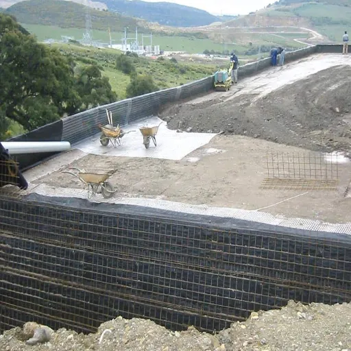
The seismic check doesn’t demand the strongest grid on the market. It demands a grid whose properties can be verified at the strain levels the design assumes.
Tensile stiffness at low strain. Seismic demand is a deformation problem. A grid that mobilizes stiffness at 2–5% strain may outperform a stronger grid that mobilizes late. Ask for the stress-strain curve, not a single ultimate value.
Junction efficiency and connection strength. The connection is where the 80% rule bites. Ask for connection shear test data for the specific facing system, not a generic grid strength.
Aperture and aggregate interlock. Interlock transfers load under cyclic shaking. The aperture must be compatible with the fill gradation. Our guide to geogrid aperture size covers the selection logic.
Polymer and durability. Polypropylene, polyester, and HDPE differ in creep, installation damage, and chemical exposure. For seismic, short-term properties matter. For the static component, creep still governs.
Documentation. Test certificates, lot traceability, retained samples, and a datasheet that states the strain at which strength is measured. This is where a supplier’s quality system becomes a design input, not a sales claim.
Send us your wall height, PGA, site class, and facing type, and our engineering team will review the specification with you. Contact engineering support for a project-specific response.
A Seismic Design Checklist for Specifiers
- Confirm seismic demand: PGA, S1, site class, and acceleration coefficient.
- Confirm whether a seismic check is required. MSE walls: coefficient above 0.05. Reinforced slopes: always.
- Complete the static design first. Seismic is an additional case, not a replacement.
- Compute kmax and kav. Note the wall-height effect.
- Choose the analysis method. Mononobe-Okabe for simple cohesionless backfill. Generalized limit equilibrium for complex geometry or c-φ soil.
- Check external sliding and compute displacement. Agree the tolerable limit, typically 50–100 mm.
- Check eccentricity and bearing with the extreme-event combination.
- Check internal rupture with the static and dynamic split. Don’t apply creep to the dynamic increment.
- Check pullout with F* × 0.8 and connections with 0.8 × static where friction-dependent.
- Detail drainage, facing connection, top-two-layer extension, and foundation improvement.
Frequently Asked Questions
Do geogrid-reinforced walls perform well in earthquakes?
Yes, generally. The reinforced mass is flexible and ductile, and Japanese GRS walls performed well in Kobe and Tohoku. Performance still depends on drainage, foundation, and connections, not on the grid alone.
What seismic coefficient is used for MSE walls?
FHWA uses kmax equal to the site factor times PGA, reduced to a height-dependent average kav. MSE walls are checked where the acceleration coefficient exceeds 0.05. Reinforced slopes are checked at any acceleration.
How much movement is acceptable?
FHWA describes typical practice as 2–4 in (50–100 mm) of lateral displacement, provided the structure above or below can tolerate it. The limit is project-specific and should be agreed early.
Why is creep ignored in seismic design?
Creep develops under sustained load. Earthquake loading is transient, so FHWA allows the dynamic component to be designed without a creep reduction factor. The static component still includes creep.
How long should geogrid be in a seismic zone?
The minimum is 0.7H or 8 ft (2.5 m). Sloping surcharge or abutment loads typically require 0.8H to 1.1H. Where seismic tension cracking is a concern, extend the top two layers by 3 ft (0.9 m).
Does groundwater affect seismic performance?
Yes. High water creates excess pore pressure during shaking, and drawdown during an earthquake can be worse because seepage drag acts outward. Drainage and filtration are seismic details.
Are geogrid walls better than concrete walls in earthquakes?
They are more flexible and tolerate deformation better. Rigid walls can crack and lose load path. The comparison is structure-specific, and foundation and drainage still govern.
Conclusion
Geogrid seismic design isn’t a separate design method. It is reinforced soil design with four numbers changed and three details promoted to governing.
The four numbers are kmax and kav, PAE, PIR, and Tmd. The three details are drainage, foundation, and connection. The acceptance criterion is displacement, not zero movement. The material rule that surprises most engineers is real: creep is excluded from the dynamic component because the load is transient.
The practical sequence: complete the static design, establish the seismic hazard, run the displacement check, split internal design into static and dynamic components, apply the 80% reductions, then inspect the details the calculation cannot fix.
If you are specifying geogrid for a seismic project, request a technical quote with your wall height, PGA, site class, and facing type. We will help you match the material data to the design assumptions.