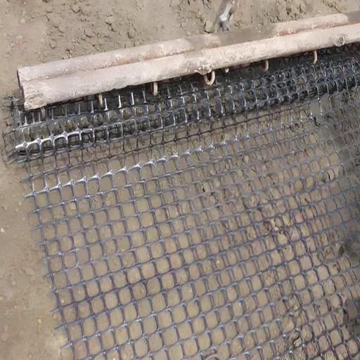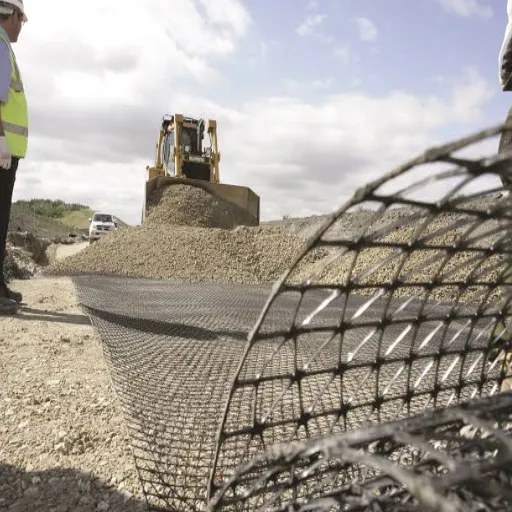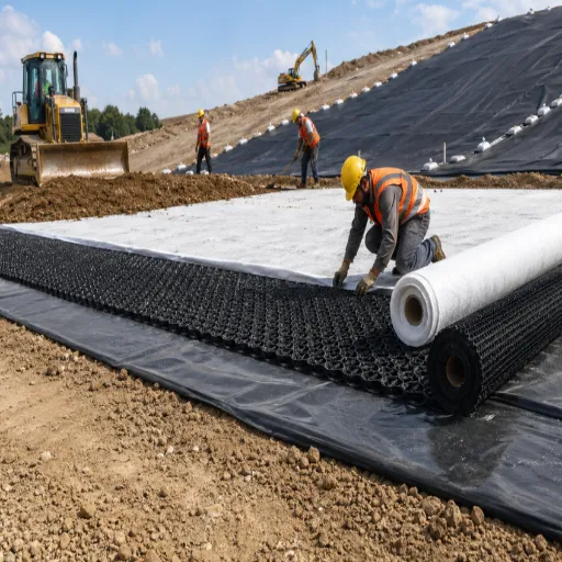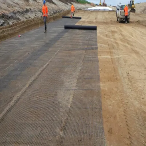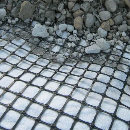
The tensile membrane effect is the vertical support a geogrid develops after it deflects into a curve. Tension in the sheet gains a vertical component, and that component carries part of the load above it. Without deflection there is no membrane effect. That is why it governs soft ground, unpaved roads, pile-supported embankments, and voids, and why it is close to irrelevant on a stiff paved road.
Consider Daniel, a site engineer on a soft-ground haul road. A supplier’s brochure said the geogrid would act as a tensioned membrane and cut the base thickness by a third. Daniel reduced the base from 600 mm to 400 mm.
The design allowed 25 mm of rut. At that deflection, equilibrium demanded several meganewtons per metre of tension. The membrane never carried the load the brochure assumed, and the road rutted to 90 mm in the first wet season.
The geogrid was not defective. The mechanism was counted at a deformation the road could not tolerate.
This guide covers the mechanics, the deformation thresholds, the applications where the effect governs, and the four checks that make it safe. For the broader reinforcement picture, start with our complete guide to geogrid soil reinforcement.
Key Takeaways
- The tensile membrane effect is vertical support from tension in a deflected geosynthetic; it requires tension, curvature, and anchorage at the same time.
- It mobilizes only at large deformation. On subgrades above CBR 3 and on paved roads, lateral restraint and interlock do most of the work.
- For a given span and load, tension falls as sag rises: a 6 m span at 20 kPa needs about 900 kN/m at 100 mm of sag and about 150 kN/m at 600 mm.
- Membrane action is a strain-compatibility problem. If the structure cannot tolerate the sag, the effect is not available, whatever the grid’s tensile strength.
- In pile-supported embankments it works with soil arching and subsoil support. In voids and sinkholes it is the primary mechanism.
What Is the Tensile Membrane Effect?
The tensile membrane effect is the vertical support generated when a geosynthetic deflects into a concave shape under load and its tensile resistance develops a vertical component. The sheet carries load in tension, the curvature turns part of that tension upward, and the anchorage outside the deflected zone keeps the sheet from being pulled in.
Three conditions must all be present:
- Tension. The geosynthetic must be able to carry tensile load, and it must be connected or embedded well enough for that load to develop.
- Curvature. The sheet must move out of plane. A flat sheet has no vertical component, no matter how strong it is.
- Anchorage. The tension must be resisted beyond the deflected zone. Without anchorage, the sheet slides rather than supports.
The equilibrium is simple. On each side of the sag, the vertical component is T sin θ, where T is membrane tension and θ is the angle of the sheet at the support. The two components together balance the load carried by the membrane.
This isn’t the same as the other reinforcement mechanisms. Lateral restraint develops through interface shear and needs no curvature. Interlock and confinement come from aggregate particles bearing on the ribs. Increased bearing capacity comes from forcing a deeper failure surface.
Soil arching is load transfer within the fill above a yielding support. The tensile membrane effect is the only one that depends on the sheet changing shape.
“Tensioned membrane effect” is the more common phrase in the research literature. “Tensile membrane effect” is the search term this article targets. They describe the same mechanism.
If you are specifying a geogrid for soft ground and want a second opinion on which mechanism is doing the work, our engineering team can review the subgrade, the fill, and the anchorage with you. Request a technical review.
The Mechanics: Why Deflection Converts Tension into Support
The mechanism is ordinary statics. For a symmetric sag under a uniform load, per unit width:
2T sin θ = qL
Here T is membrane tension, θ is the angle at the support, q is the load per unit area carried by the membrane, and L is the span. For small sag, the parabolic approximation is accurate enough for screening:
T ≈ qL² / (8δ)
where δ is the maximum sag. Rearranged, the membrane support pressure is p = 8Tδ / L². Tension and sag are inversely related. Doubling the sag halves the tension, but it doubles the settlement.
Take a 6 m span carrying 20 kPa, a screening case for a void or a very soft pocket:
| Maximum sag | Membrane tension | What it means |
|---|---|---|
| 100 mm | about 900 kN/m | Beyond most geogrids |
| 200 mm | about 450 kN/m | High-strength grid territory |
| 300 mm | about 300 kN/m | Achievable with a strong grid |
| 600 mm | about 150 kN/m | Modest grid, large settlement |
The table is the argument in four rows: a membrane converts settlement into tension. If the structure cannot settle, the required tension becomes enormous.
That’s why membrane action is a strain-compatibility problem, not a strength-only problem. For a given sag and load, equilibrium fixes the tension. The geogrid’s load-strain curve then decides whether it can reach that tension at an acceptable strain.
A stiff grid needs less sag but develops tension quickly. An extensible grid sags more and carries the same load at lower tension.
Anchorage is part of the mechanism. The tension T must be resisted outside the deflected zone by embedment, friction, or fixation. Pullout capacity and junction strength can govern before the sheet’s tensile strength does.
A grid with a high ultimate strength and a short anchorage length isn’t a membrane. It’s a sheet that pulls in.
The equation is a screening tool, not a design method. In a pile-supported embankment, three-dimensional arching and subsoil support carry part of the load, so the membrane demand is lower than a two-dimensional span calculation suggests. For the relationship between reinforcement and bearing failure, see our guide to geogrid bearing capacity.
When Does the Membrane Effect Actually Mobilize?
The membrane effect is a large-deformation mechanism. It appears after the support beneath the geosynthetic yields, and it grows as the geosynthetic curves. Three conditions decide whether that happens in a real structure.
Subgrade strength. Zornberg’s review, citing Barksdale et al., reports that the membrane effect develops only where the subgrade CBR is below about 3. On firmer ground, the subgrade does not yield enough, and lateral restraint and interlock carry the load.
Tolerable rut depth. On unpaved roads, rut depths in excess of 25 mm may be acceptable. On paved roads, the same rut is a failure, and the deformation required to mobilize the membrane generally exceeds the serviceability limit.
Design method. Giroud and Han’s method for geogrid-reinforced unpaved roads uses rut depth as the design criterion and treats the membrane effect as one contribution alongside lateral spreading. It works because the road is allowed to deform. A paved road designed to a 10 mm surface tolerance is not.
The practical thresholds look like this:
| Application | Deformation typically available | Membrane contribution | Mechanism that usually governs |
|---|---|---|---|
| Paved road or stiff platform | 25 mm or less | Small to negligible | Lateral restraint, interlock |
| Unpaved haul road | 25 to 75 mm or more | Moderate | Interlock plus membrane |
| Working platform on very soft ground | 50 to 150 mm | Moderate to high | Membrane plus confinement |
| Pile-supported embankment | 50 to 200 mm differential | High | Soil arching plus membrane |
| Void or sinkhole bridging | Hundreds of mm | Dominant | Membrane |
These ranges are indicative, not code limits. The design still has to check the actual serviceability limit.
If the structure’s allowable deformation is smaller than the sag needed to develop the required tension, the tensile membrane effect is not available. It belongs in ultimate-limit and robustness checks, not in serviceability calculations. A supplier who quotes membrane capacity without stating the deflection has not given you a design value.
For soft-ground platforms, the section design and the separation layer matter as much as the grid. Our guide to geogrid for soft ground covers the CBR selection and installation side.
Membrane Effect vs Lateral Restraint: Which One Is Doing the Work?
The research literature usually lists three reinforcement mechanisms: lateral restraint, increased bearing capacity, and the tensioned membrane effect.
Lateral restraint develops through interface shear between the aggregate and the geosynthetic. When a wheel load pushes the base sideways, the grid resists the movement, and the base layer stays confined. The mechanism needs no curvature and mobilizes at small strain. It depends on aperture-aggregate compatibility, rib profile, and junction efficiency.
Membrane action needs curvature and large strain. It dominates only where the support yields: very soft ground, unpaved roads at high rut, pile-supported embankments, and voids. It depends on tensile stiffness, anchorage, and strain compatibility.
Both mechanisms can be present in the same layer. The question is which one carries the design load at the deformation the structure can tolerate. On a paved road with a tight surface tolerance, restraint does the work and the membrane is reserve capacity.
On a haul road that can rut, the membrane becomes a legitimate contributor. On a void, it is the primary mechanism.
Why do suppliers disagree? Because each is describing a different application. A supplier selling into paved roads emphasizes restraint because that is what the application mobilizes. A supplier selling into soft-ground platforms or embankments may emphasize the membrane because that is where it is real.
Both claims can be correct. The error is carrying one application’s claim into the other.
The decision rule is simple. If the design allows less deformation than the membrane needs, design for restraint and interlock, and treat membrane action as reserve. If the design can tolerate the settlement, the membrane is a design mechanism and must be checked as one. For the full mechanism family, including interlock and the soil-geogrid interaction model, see how geogrid reinforcement works.
Where Membrane Action Governs

Unpaved roads and haul roads
The membrane effect is one of the mechanisms in the Giroud-Han design method, alongside lateral spreading and bearing capacity. Rut depth is the design criterion. The road is allowed to deform, which is exactly why the membrane is available.
The benefit diminishes as base thickness increases. A thick, stiff base spreads the load before the geosynthetic has to act as a membrane. This is why membrane claims are strongest on thin, unpaved sections over weak subgrade, and weakest on thick, well-compacted pavements.
Working platforms on very soft ground
A working platform deflects under plant load. The geogrid mobilizes tension and reduces the stress delivered to the subgrade. Separation is usually needed as well, because fines can migrate into the granular layer and contaminate it.
Edge anchorage is critical. A platform membrane must be anchored beyond the loaded area, or the whole sheet pulls inward. The anchorage check often governs the design, not the tensile strength.
Pile-supported embankments
A geosynthetic-reinforced pile-supported embankment transfers load through three components: soil arching in the fill, membrane action in the geosynthetic, and subsoil support beneath the embankment. Design methods such as EBGEO, BS 8006-1, and CUR 226 treat the geosynthetic as a tensioned membrane spanning between pile caps after arching has transferred part of the load to the piles.
Tension depends on the clear span between pile caps, the fill height, the subsoil support, and the differential settlement the geosynthetic can tolerate. The membrane effect is higher when the geosynthetic is stiff and close to the pile heads. A second geosynthetic layer only helps if punching occurs.
Arching and membrane share the load. Adding the full membrane capacity on top of full arching is unconservative. The reinforced soil design framework covers how the components are combined.
Voids, sinkholes, and cavities
This is the case where membrane action is unambiguously dominant. The geosynthetic bridges a void and carries the soil above it in tension. Feng, Ai, and Chen give an analytical treatment for localized sinkholes, and Wang, Feng, and Jao cover the stability of reinforced soil above a cavity.
Design for two things: tension in the sheet and surface deflection above the void. Anchorage beyond the void edge is critical. The required tension depends on the assumed void size and the consequences of surface settlement.
Designing for Membrane Action: Four Checks
Four checks cover the mechanism.
- Tension demand. Calculate T from equilibrium at the design deflection, using factored loads. State the assumed span, load, and sag. If the sag is not stated, the tension isn’t verifiable.
- Long-term strength. Compare the demand with the geogrid’s long-term design strength after creep, installation damage, and durability factors. The framework is LTDS = UTS / (RF_CR × RF_ID × RF_D); our guide to geogrid creep explains each factor.
- Anchorage and junctions. Check pullout beyond the deflected zone and junction efficiency. The membrane is only as strong as its anchorage. See pullout resistance and anchorage for the test and design side.
- Deformation compatibility. Confirm that the sag needed to develop the tension is within the structure’s serviceability limit. If it isn’t, the membrane effect can’t be counted, regardless of the grid’s strength.
| Check | Question | Data needed | If it fails |
|---|---|---|---|
| Tension demand | What tension does equilibrium require at the design sag? | Span, load, assumed deflection | Increase strength or reduce span and load |
| Long-term strength | Can the grid hold that tension for the design life? | Creep-reduced strength, RF_ID, RF_D | Specify a higher LTDS |
| Anchorage | Can the ends develop the tension? | Pullout data, embedment length, junction efficiency | Extend anchorage or add fixation |
| Deformation | Is the required sag acceptable? | Serviceability limit, predicted settlement | Do not count membrane action |
The membrane effect isn’t a small-strain mechanism. It isn’t a substitute for interlock in a paved road. It isn’t a justification for arbitrary base-thickness reduction.
It also isn’t the same as soil arching. And it isn’t proven by ultimate tensile strength alone. Those five negatives resolve most of the confusion in supplier literature.
How to Specify and Verify Membrane Capacity

A credible membrane specification states the strain, the design life, and the anchorage condition. Ask for:
- Tension at a stated strain, not just ultimate tensile strength
- Long-term design strength for the project design life
- Junction efficiency
- Pullout or anchorage test data
- Installation damage reduction factor
- Test standards: ASTM D6637 or ISO 10319 for tensile properties, ASTM D5262 for creep, and project-specific pullout tests
Red flags are easy to spot once you know the mechanism:
- Ultimate tensile strength quoted as if it were the design tension
- A membrane claim on a paved road with a tight surface tolerance
- No strain or deflection stated alongside the tension
- No anchorage or junction data
- Generic “high tensile strength” language with no test report
Compare products only after matching the design strain, design life, and anchorage condition. A higher-UTS grid is not automatically a better membrane.
If you are comparing geogrids for a membrane application, send the subgrade profile, the span, and the allowable settlement to our team. We can review the mechanism and the test data together. Request geogrid test data or contact engineering support.
Frequently Asked Questions
What is the tensile membrane effect?
The tensile membrane effect is the vertical support a geosynthetic provides when it deflects into a curve and its tension develops an upward component. It requires tension, curvature, and anchorage. A flat sheet carries no membrane load, however strong it is.
When is the membrane effect mobilized?
Only at large deformation. It is associated with subgrades below about CBR 3, unpaved roads where ruts of 25 mm or more are tolerable, soft working platforms, pile-supported embankments, and voids. On stiff paved roads, the deformation needed usually exceeds the serviceability limit.
Does the membrane effect work on paved roads?
Only marginally. The deformation needed to mobilize it generally exceeds the pavement’s serviceability limit. Lateral restraint and interlock do most of the work in a paved road. A membrane claim on a paved section should be treated as reserve capacity, not design capacity.
Is the membrane effect the same as soil arching?
No. Soil arching is load transfer within the fill above a yielding support. The membrane effect is tension in the reinforcement. In a pile-supported embankment they act together, along with subsoil support, and the load must not be counted twice.
Conclusion
The tensile membrane effect is real, but it is conditional. It needs tension, curvature, and anchorage. It appears only after the support yields, and the design is a trade between tension and settlement.
That makes it an ultimate-limit mechanism, not a serviceability mechanism. On paved roads and stiff platforms, lateral restraint and interlock do the work. On soft ground, unpaved roads, pile-supported embankments, and voids, the membrane can govern.
The difference isn’t the product. It’s the deformation the structure can tolerate.
Before you accept a membrane claim, ask for the strain, the design life, and the anchorage data. If the structure can’t sag enough to develop the tension, the tensile membrane effect isn’t available, and a stronger grid won’t change that.
If you need help matching a geogrid to a membrane application, contact our engineering team with the span, the load, and the allowable settlement. We will review the mechanism and the test data with you.
Sources
- Zornberg, J. G. (2014). Advances in the Use of Geosynthetic Reinforcements for Paved Roads.
- Giroud, J. P., and Han, J. (2004). Design Method for Geogrid-Reinforced Unpaved Roads. I: Development of Design Method. Journal of Geotechnical and Geoenvironmental Engineering, 130(8), 775-786.
- Feng, S. J., Ai, S. G., and Chen, Y. (2018). Membrane effect of geosynthetic reinforcement subjected to localized sinkholes. Canadian Geotechnical Journal, 55(9), 1334-1348.
- Wang, M. C., Feng, Y., and Jao, M. (1996). Stability of geosynthetic-reinforced soil above a cavity. Geotextiles and Geomembranes, 14(2), 95-109.