Choose a geomembrane electrical leak location method by checking whether the liner will be exposed or covered. Then check the layer drawing and the path that current can take back to the equipment. The instrument name alone cannot tell you whether a survey will work.
It’s easy to ask for a spark test before anyone has identified the layer beneath the liner. That missing detail can change the recommendation. This guide compares the main methods and explains which questions to resolve with a qualified survey specialist before you commit to one.
Start by collecting your liner specification and section drawing. Use our HDPE geomembrane information to frame material questions, then bring the installed system details to the survey discussion.
Key takeaways
- Exposed and covered liners require different survey approaches.
- Standard high-density polyethylene (HDPE) can be a candidate. A conductive backing suits certain methods, not every test.
- Check contact, current flow and isolation. Each can affect whether the proposed circuit will work.
- Finding a hole does not prove seam strength or show whether the liner will leak in future.
- Ask for proof the method works at your site and a clear account of the areas it can check.
What geomembrane electrical leak location can tell you
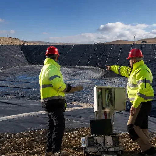
Electrical leak location (ELL) finds holes or other breaks by tracing current through a liner. An intact liner acts as an electrical barrier. A hole, cut or tear can create a path for current through that barrier. The layers around the liner must allow the method to detect that path.
ASTM D6747-25 describes the selection of electrical techniques for installed geomembranes. Its public scope distinguishes finding where a leak is from finding that a leak exists. Use that distinction when you ask a team to locate an area for inspection or repair.
A leak path is different from seam strength
A survey may locate a breach at a seam or within a sheet. It does not measure the strength of an intact weld or establish the material’s other properties. The public scope of ASTM D7703-22 makes this limit clear. Finding a leak does not verify the material or seam integrity.
Keep the specified welding checks in the construction quality assurance (CQA) program. Our geomembrane seam testing guide covers that adjacent subject. ELL asks a different question: where can current pass through the barrier under the test conditions?
A survey describes a defined condition
A one-time ELL survey differs from a system that monitors the liner over time. A survey describes the tested area at a particular construction stage. It cannot tell you what happens after later traffic, cover placement or repairs unless those conditions are assessed too.
Illustrative scenario A: An engineer has an exposed conventional HDPE liner and a request for electrical testing. The drawing does not identify the layer directly beneath it. Before choosing equipment or buying a different liner, the engineer needs that missing section information and a specialist’s assessment of the return path.
This example assumes no test result. It shows why ELL starts with the installed system. Ask what the proposed survey can establish, which areas it can reach and what would prevent a meaningful result. No breaches detected is useful only when you know those limits.
Compare geomembrane electrical leak location methods
First, identify the liner’s state at the time of the survey. Will it be exposed, under water or beneath soil? Next consider the backing and surrounding layers.
The table compares candidate methods and the questions that can change the choice. Use it to discuss your site with the specialist.
| Method and reference | Survey state | Electrical path or backing | Practical dependency to confirm |
|---|---|---|---|
| Water puddle, ASTM D7002-22 | Exposed | Suitable path through breaches to the return side | Water supply, surface access, contact and isolation |
| Water lance, ASTM D7703-22 | Exposed | Water-based path through a breach | Water application, geometry, access and return-path feasibility |
| Arc, ASTM D7953-20(2024) | Exposed | Suitable conductive return path | Surface condition, contact, equipment suitability and safe access |
| Conductive-backed spark, ASTM D7240-25 | Exposed compatible liner | Insulating layer in intimate contact with a conductive layer | Backing construction, installed details and equipment compatibility |
| Covered survey, including dipole approaches; ASTM D7007-24 and D8265-26 | Water or earthen cover | Feasible conductive path on the relevant sides of the barrier | Cover condition, contact, isolation and demonstrated capability |
Use these references to make a survey proposal more specific. A method label should lead to an explanation of why the site supports it. Which condition makes this method a candidate? Ask for that link between the equipment and the site, not just the test name.
Water puddle and water lance
Water puddle and water lance are exposed-liner methods. Both bring water into the survey process, but they have distinct practices. Check the circuit first. Then ask whether crews can apply water across the whole area.
For water-based surveys, ask who supplies water, how crews reach the surface and how slopes affect coverage. These questions belong in planning before mobilization. Water availability alone does not confirm that current can return through the layers beneath a breach.
Standard insulating HDPE is not ruled out. In a suitable system, an electrical survey can work without a built-in conductive backing. But the name HDPE alone does not tell you which water-based method will work.
Keep water puddle and water lance as separate options. Ask the specialist to check the layers and shape of the site. Don’t choose between them using an advertised production rate from a different site. The practice, site conditions and proposed coverage need to agree.
Arc testing and conductive-backed spark testing
Arc and conductive-backed spark testing are not interchangeable names. Arc testing has its own exposed-liner practice, ASTM D7953. The conductive-backed spark practice uses a specific layer arrangement and a capacitance technique.
Capacitance is an electrical property of that layer arrangement; it is not a general label for all spark tests.
ASTM D7240-25 addresses geomembranes whose insulating layer is in intimate contact with a conductive layer. That layer arrangement is central to its scope. The word conductive in a product description is not enough. Ask whether the installed liner and proposed equipment suit the method.
Our conductive HDPE geomembrane guide explains the material category. Take the actual backing specification to the survey provider. Ask which parts of the installation support the proposed spark technique and how details outside that arrangement will be handled.
For arc testing, ask about the required surface state, return path and access around wrinkles and details. A test without water still needs the right circuit and site conditions. Check contact and safe access before choosing it.
Also distinguish a sheet-area survey from a test restricted to seams. The word spark by itself leaves that scope unclear. State the area you need checked in your request.
Surveys through water or earthen cover
Covered-liner surveys use a different way to measure signals. The team measures through the water or soil above the liner. It does not move exposed-liner equipment directly across the sheet. The type and state of the cover help determine which method can work.
ASTM D7007-24 addresses geomembranes covered with water or earthen materials. Its public description calls for site checks and proof of leak-detection capability. ASTM D8265-26 addresses electrical mapping in covered installations.
For covered-liner surveys, match these references to the proposed work. Neither name means the method suits every site.
Ask how the specialist will show the method works in the actual cover. How will the report record conditions that limit the test? A detection claim from another pond or soil profile cannot substitute for that discussion. Avoid assuming a universal cover depth, grid spacing or minimum detectable hole size.
Illustrative scenario B: A double-lined facility includes a dry drainage space between its barriers. The team wants an ELL method but has not established which barrier and conductive path the survey would assess. First, resolve which layers the survey must assess. A generic diagram cannot tell the team to add water or change the liner.
Choose the survey stage before cover placement
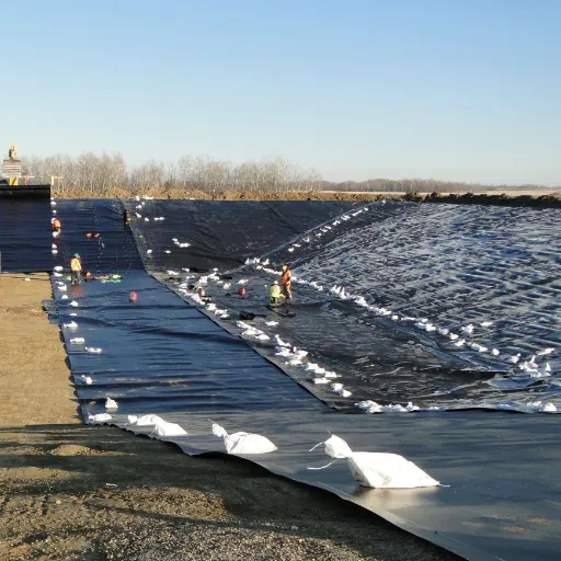
When you survey the liner changes the question you can answer. An exposed survey after welding assesses the liner before later cover work. A covered survey can address the condition after that work, when the site supports the proposed method.
For a visual introduction, watch the Fabricated Geomembrane Institute webinar Electrical Leak Location (ELL): Planning & Preparation, presented by Andrew Colby on 16 January 2024. Use it to frame questions for the survey team; it does not replace the current project specification.
Preserve the exposed-stage opportunity
Exposed access gives the survey team direct access to the liner surface. It also lets the project team plan inspection and repair access before material covers the area. Ask the design and CQA team where this stage fits. It needs a place alongside welding checks and other acceptance work.
Confirm what will happen between testing and cover placement. Will crews work on the area again? Are penetrations, details or repairs still incomplete? These questions define what the result will cover.
The right sequence still depends on the project.
Discuss the survey window alongside the geomembrane installation sequence. Discuss it with the construction manager, installer and survey provider. The survey stage needs to match the work that will be complete.
If cover crews arrive first, review the test plan. It may no longer describe the site.
Cover placement creates another verification question
D7007 identifies damage during construction and placement of material over the liner as a reason for covered surveys. A survey before cover placement cannot show the condition after later work. Does the project need both stages? The answer depends on the design, acceptance requirements and what the site allows.
Solmax’s industry article Do you care if it leaks?, dated 18 August 2026, discusses planning verification for heap-leach liners before cover-related decisions become fixed. It supports early planning. It does not set a new legal deadline or a product rule for every site.
Illustrative scenario C: A team has an ELL record from before soil placement. Later, another contractor places the cover. When the owner asks about the covered condition, the team must distinguish the earlier result from any later verification. Nothing in this example assumes damage occurred or that a particular survey would find it.
Bring the cover schedule and liner section to the design and survey team before booking the work. Agree which construction stage needs evidence, who releases the area and how repairs or later work affect that decision. Agree these points so everyone knows the scope before the test starts.
Confirm site conditions before accepting a method
An electrical survey recommendation should explain why the proposed circuit will work. Check conductivity, contact and isolation as separate issues. Conductivity means the ability to carry current; isolation keeps current from taking an unwanted route around the liner.
A layer that carries current cannot help if the path is broken. Good contact does not rule out a bypass elsewhere.
- Can current follow the intended path? Identify the layers above and below the barrier, including drainage and protection layers. Wrinkles or bridging can interrupt contact. A drawing alone cannot confirm field contact across the whole area.
- Can current bypass the liner? Identify penetrations, metal details and perimeter connections. D6747 explains that these paths can mask leak signals. Ask the specialist whether they can be isolated, including connections outside the main floor area.
- Will the surface suit the method? Check the need for water application or a dry, clean surface. Weather and site work can change these conditions. Agree how the team will respond if the surface differs from the plan.
- Can the team reach each zone? Slopes, walls, folds and tight spaces can limit access. Ask how the coverage plan accounts for them. Record any strip that cannot be reached and what the team proposes to do about it.
- Who controls safe access? Electrical methods need qualified, experienced staff and suitable safety controls. Ask the provider for a site-specific work procedure that protects staff and other people nearby. Equipment settings belong in that procedure, outside this selection guide.
Returning to scenario B, the dry drainage space is an unresolved system detail, not proof that ELL is impossible. Ask the specialist to review the intended path. Apply the same check to conductive backing. Confirm the installed layers and proposed test; the product label alone cannot show whether the test will work.
Before you accept the method, ask for a demonstration that it works at your site. Request a list of areas or conditions it cannot assess. Agree who will confirm each condition on site. Put unresolved items back to the design and survey team before fixing the method.
If conditions change, the survey basis may need review. A useful proposal says what must be true for the method to work and who will confirm it. It does not transfer an advertised detection limit unchanged to every installation.
What evidence should accompany the recommendation?
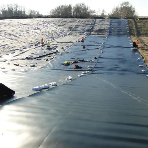
A useful ELL result is more than a pass label. You need to understand what was assessed, when it was assessed and what the method could establish. Use the list below to frame your request. It is buyer guidance, not a list of mandatory ASTM report clauses.
- Method rationale: Name the method and explain why the liner, backing and cover state support it.
- System description: Reference the section drawing and identify the barrier being assessed in a multilayer system.
- Survey stage and coverage: Identify the tested area, construction stage and any excluded or inaccessible zones.
- Demonstrated capability: Explain how capability was checked under the survey conditions and state the relevant limitations.
- Defect follow-up: Connect located defects with inspection, repair and retest records where applicable.
Ask the provider to explain any survey exclusions in plain language. If a zone could not be assessed, you need its location and the reason. The project team can then choose its next step. It could change the conditions, seek another approach or accept the stated limit.
Keep tested and untested areas distinct in the report.
In scenario C, the first question is whether the record describes the pre-cover or post-cover condition. Check that distinction first. The earlier result does not describe the later covered condition. Dates and construction-stage descriptions matter alongside a coverage drawing.
Keep electrical survey evidence alongside the relevant installation and seam records. They describe different parts of quality assurance. One record does not take the place of another.
You can assess a recommendation when its method, physical basis and limits are clear. A sales promise cannot supply those details.
Questions to resolve before choosing the next step
Can conventional HDPE undergo an electrical leak survey?
Yes, standard insulating HDPE can be a candidate for ELL when the installed system supports the chosen method. Conductive backing is required for specific techniques, not every electrical survey. The specialist still needs to assess the substrate, contact, electrical isolation and the liner’s exposed or covered state.
Are arc testing and spark testing the same?
No. Arc testing and conductive-backed spark testing have distinct ASTM practices and different system requirements. The spark method needs close contact between an insulating layer and a layer that carries current. Ask which practice the provider proposes and whether the scope covers sheet areas, seams or only particular installed details.
Can a geomembrane be tested after it is covered?
Yes, survey methods exist for water-covered and earth-covered liners. The cover, current path, contact and isolation all affect whether they will work. Ask the provider to demonstrate capability under the actual conditions and explain coverage limits. An exposed-liner test name alone does not specify a covered survey.
Does electrical leak location replace weld testing?
No. ELL can locate holes and other breaks, including openings at seams. It does not measure weld strength or the liner’s other properties. Retain the project’s specified seam and material checks. Use the survey alongside those checks, with a clear scope and limits of its own.
Does a survey guarantee future containment?
No. A survey describes the tested area under the conditions present during that work. Later construction, repairs and changes in service are separate considerations. Read a result with no detected holes alongside the proof of capability and the areas that were not tested. It is not a guarantee against future leakage.
Before choosing your next step, gather the liner specification, complete section drawing, cover state and construction schedule. These details turn a broad request into questions a qualified specialist can assess. In scenario A, completing the missing drawing is more useful than selecting an instrument from its name.
For material selection, review our HDPE liner information and identify the installed liner and backing accurately. Then take the full system details to your survey specialist to discuss geomembrane electrical leak location, the area to be assessed and the evidence your project needs.