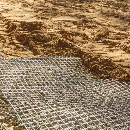
GCL installation follows nine steps. Verify and compact the subgrade, then confirm dry conditions and inspect the rolls. Deploy panels downslope in a shingled orientation and form 150 mm longitudinal and 500 mm end-of-roll overlaps. Apply supplemental bentonite at 0.4 kg per linear metre and anchor at trenches or runout anchors. Hold for CQA inspection, then cover the same working day with at least 300 mm of approved soil.
Every dimension in that sequence exists for a mechanical reason, and the reason matters more than the number. A factory-certified geosynthetic clay liner leaves the plant with an index flux printed on its certificate. What that liner achieves in a landfill cell, a reservoir, or a heap leach pad is decided by the crew on site.
When a containment system underperforms, the investigation rarely ends at the bentonite supplier. It ends at a separated overlap, a panel that hydrated before its cover arrived, or cover soil placed too thin for the traffic running over it.
Key Takeaways
- ASTM D6102 sets the floor at 150 mm longitudinal and 500 mm end-of-roll overlaps. Where a project specification or manufacturer manual requires more, the larger dimension governs.
- Overlaps without supplemental bentonite leak up to 8 times more, and one 300 mm overlap retained only about 32% of its width after 28 months of shrinkage.
- Premature hydration is the most expensive installation failure. Unconfined bentonite swells without restraint, loses density, and never forms the specified seal.
- Cover the GCL the same working day with at least 300 mm of soil, and keep all plant off the liner itself.
- The pre-cover CQA hold point is the last inexpensive moment to catch a defect. Once soil is placed, seams and hydration state are effectively unverifiable.
Ready to compare products on test data rather than brochures? Contact our engineering team for a technical quote with ASTM test reports and retained samples.
GCL Installation: The 9-Step Sequence
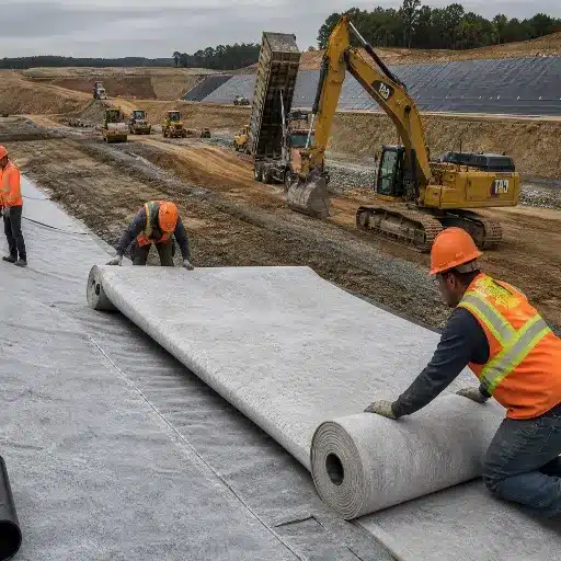
- Verify the subgrade is smooth, firm, compacted to specification, and free of protrusions.
- Confirm conditions are dry, with no standing water, rain, snow, or heavy fog.
- Inspect and store rolls off the ground and under tarp, quarantining anything damaged or wet.
- Deploy panels downslope, shingled in the direction of grade, using a spreader bar and never dragging the roll.
- Form overlaps at 150 mm minimum longitudinally and 500 mm minimum end-of-roll.
- Apply supplemental bentonite at 0.4 kg per linear metre across the full overlap width.
- Anchor at trenches or runout anchors, with pins at 300 to 500 mm on slopes.
- Hold for inspection and written CQA approval before any cover material is placed.
- Cover the same day with at least 300 mm of approved soil, using low-ground-pressure equipment only.
The GCL installation order is not negotiable, and step 9 is the one crews break most often.
Subgrade Preparation and Roll Storage for GCL Installation
The subgrade is the first place a project goes wrong, and it goes wrong quietly.
The surface must be smooth-drum rolled and free of abrupt elevation changes, voids, cracks, vegetation, ice, and loose debris. ASTM D6102, the standard guide for GCL installation, caps rut depth at 25 mm and requires protrusions above 12 mm to be removed, crushed, or pushed in. Compaction is commonly specified above 85% Standard Proctor, with landfill specifications often reaching 95%. Round corner radii to at least 300 mm.
On rocky ground, place and compact a 100 to 200 mm cushion of sand or fine-grained soil rather than trying to pick every stone out of a natural subgrade.
The purpose is contact. A GCL needs intimate contact with the soil beneath it, because soft spots and desiccation cracks create preferential flow paths under the liner. No amount of careful seaming above them will fix that.
Store rolls on dunnage, under waterproof tarps, out of standing water and away from UV exposure. Remove packaging immediately before GCL installation, not the day before, and quarantine any roll that has been wet. A roll that sat in a puddle for a week already has a partly hydrated core, and that panel will not perform. For panels over roughly 30 m, use steel cores; a cardboard core collapses during deployment and drags bentonite off its own edge.
Deployment Direction, Panel Orientation & Shingling
Deployment direction controls where water goes, which is the entire point of a hydraulic barrier.
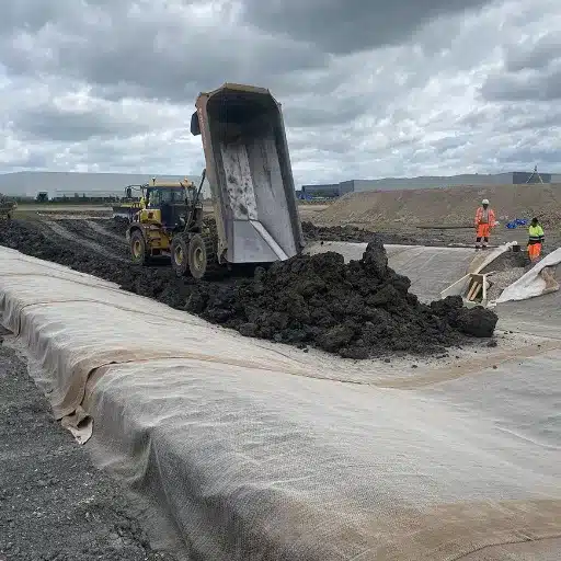
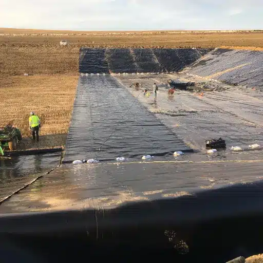
Deploy panels downslope, from crest to toe, and never horizontally across a slope. On inclined surfaces, lay panels parallel to the slope direction and along their length, so the material does not sag under its own hydrated weight and pull its own overlaps apart. Shingle in the direction of grade, so surface water runs over the seam rather than into it. On a floor, the upgradient panel laps over the downgradient panel.
Get this backwards and every seam becomes a funnel.
Set geotextile orientation per the drawing rather than by habit. Most products specify the nonwoven cover geotextile facing up to maximise interface shear resistance. Reinforced, non-reinforced and geomembrane-laminated grades differ in exactly these handling details, so it is worth reviewing the main types of geosynthetic clay liner before the rolls land.
Handle rolls with a spreader bar and avoid dragging a GCL across the subgrade, which abrades the base geotextile and disturbs the bentonite. Stagger your seams, because continuous seams that align through the liner create a single continuous weakness. Needle-punched GCL seams should also sit at least 1.5 m from any overlying geomembrane seam, which matters when the design is a composite liner system.
GCL Overlap Requirements
Overlap width is the most-specified and least-understood dimension in GCL installation.
| Condition | Minimum overlap | Supplemental bentonite |
|---|---|---|
| ASTM D6102 minimum, longitudinal (sides) | 150 mm | Per manufacturer or project specification |
| ASTM D6102 minimum, end-of-roll | 500 mm | Recommended |
| UFGS 02 61 13, sides / ends | 150 mm / 500 mm | 0.37 kg per linear metre minimum |
| Typical manufacturer, longitudinal | 150 mm | Bead about 75 mm from the edge |
| Pond and reservoir applications | 300 mm | Required regardless of product |
| Manufacturer end-of-panel seam | 600 mm | Continuous bead 300 mm from the panel edge |
| Film-laminated composite GCL | 100 mm | Mastic-sealed |
| High-head applications, over 300 mm head | 300 mm | Required |
| Repair patch | 300 mm on all sides | Continuous 150 mm fillet at 0.4 kg/m |
Read that table in the correct order of authority. ASTM D6102 is a guide, and it says so in its own scope. Where the project specification or the manufacturer’s published requirements demand more, the larger dimension governs. If a landfill specification calls for 300 mm sides and a manual allows 150 mm, you install 300 mm.
Overlap dimensions are not arbitrary. A Geosynthetic Institute review identified three mechanisms that open gaps in GCL panels: shrinkage from cyclic wetting and drying, tensioning of the liner down a steep slope, and contraction across a relatively flat surface. Each pushes panels apart after installation, and each is worse at the low end of the overlap range.
The field evidence is blunt. Overlaps installed without supplemental bentonite leaked up to 8 times more than seams with it, and in one monitoring programme a 300 mm overlap retained only about 32% of its width after 28 months of shrinkage. Design for the panel the liner becomes in year three, not the panel that leaves the truck. Because seam quality feeds the flow rate the liner achieves in service, these overlap rules are also the first control on GCL hydraulic conductivity.
Keep the overlap zone clean. Loose soil, sand, debris, water, and dew all degrade a seam, and dew is the one crews dismiss.
Supplemental Bentonite at Overlaps and Penetrations
Supplemental bentonite is the cheapest intervention on any GCL site and the one most often skipped under schedule pressure.
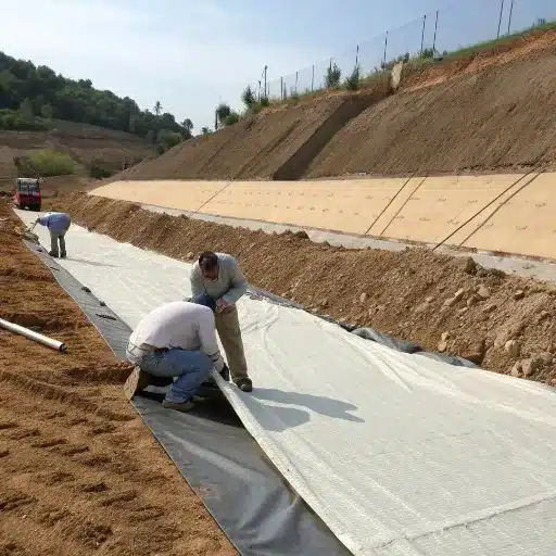
The minimum rate is 0.4 kg per linear metre of overlap, matching the 0.25 lb per linear foot figure in manufacturer manuals and the 0.37 kg per linear metre floor in UFGS 02 61 13. Placement changes by product and application: about 75 mm from the underlying panel edge on reinforced-grade longitudinal seams, about 150 mm from the edge on pond products, and up to 300 mm from the panel edge on end-of-panel seams.
Some products self-seam longitudinally through grooved or pre-coated edge strips and may not need supplemental bentonite on the sides. Ponds are the exception: there, supplemental bentonite is required in longitudinal seams regardless of what the product claims. Spread it as a continuous bead or fillet across the full overlap width; some specifications add a 100 mm wide by 5 mm thick bentonite layer plus mastic for a double seal.
Penetrations deserve the same care as seams and usually get less. Around a horizontal pipe, notch the subgrade, backfill with granular bentonite, and place a secondary GCL collar between the primary layer and the collar. A “star” cut in the collar improves the fit. Vertical penetrations are completed with two GCL pieces or a collar, and a GCL boot secured around the pipe is another common solution.
In an overlap, supplemental bentonite is the only barrier present. Without it, the seam is a mechanical lap that depends entirely on two panels staying pressed together. With it, the seam is a hydraulic seal that repairs itself as the panels move.
GCL Anchoring: Anchor Trenches, Runout Anchors & Pin Spacing
A hydrated GCL panel on a slope is a heavy, lubricated sheet. Anchoring keeps it in place while the bentonite swells and the cover arrives.
Use an anchor trench on any surface steeper than about 7:1. A typical detail runs 450 mm deep and 300 to 500 mm wide, set at least 1 m back from the crest, with the front edge rounded so the liner does not concentrate stress over a sharp corner. Clear the trench of debris and loose material, lay the GCL on the inside wall and base with about 300 mm of extra length, then backfill and compact with low-permeability soil.
Where a trench is used, pins are not required. The alternative is a runout anchor, where the roll end extends back from the crest and cover soil is placed over it, to a length set by the drawings.
Where pins are used, space them 300 to 500 mm apart on slopes and vertical faces, and no more than 500 mm apart on flat surfaces, working from the top down. Use washer-and-pin assemblies rather than bare nails, which tear through geotextile under load. Two prohibitions are worth stating outright: do not nail or staple overlaps to the subgrade, and do not rely on cover soil alone to hold a panel on a steep slope during hydration, because the panel is most mobile before the bentonite swells and locks it in place. Where wind is a risk, weight deployed panels with sandbags or tyres.
Hydration Control: The Failure Mode That Costs the Most
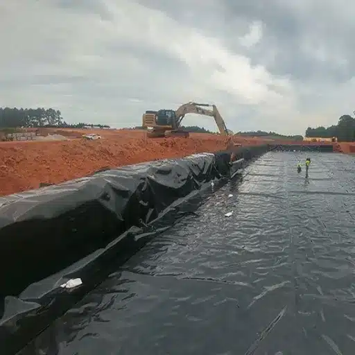
If you take one section from this guide onto site, take this one.
Sodium bentonite is designed to hydrate under confining stress, after the cover or geomembrane is in place. Unconfined hydration is a different process. The clay swells freely with nothing pressing back, loses density, and can no longer form the low-permeability seal it was specified to deliver. Overlaps are the most vulnerable zones, because the bentonite there is exposed on both sides.
Rain and stormwater are the obvious sources, with snowmelt and inadequate end-of-day covering close behind. A third mechanism catches out even experienced crews: daily thermal cycling. Day and night temperature swings condense water vapour on the underside of geomembrane wrinkles, and that condensate drips onto the GCL below, locally hydrating it, dislodging bentonite, and starting erosion at the earliest stage of the liner’s life. Field investigations have recovered samples showing localised hydration tracking precisely to wrinkle locations and wrinkle-overlap intersections.
How to detect premature hydration
Walk the panel, then confirm. Soft zones, footprints that hold their shape, and visible impressions all indicate localised hydration. Cut a sample: if the granular bentonite structure cannot be discerned in the cut face, treat the area as hydrated.
Test moisture by ASTM D2216. In one documented landfill case, background panels read around 20% moisture while hydrated areas read around 50%.
Apply the replacement threshold contract specifications use, where a panel more than 10 mm thick or with bentonite moisture above 40% is significantly hydrated and must be replaced.
A CQA inspector named Priya found exactly this on a landfill cell in 2023. A weekend storm had passed over a 900 m² section the crew left uncovered, and the giveaway was not the surface but the footprints. Walking the panel, she could feel soft pockets where installers had stepped. Cut samples confirmed the bentonite structure was gone, and that section was replaced at a cost far exceeding every bentonite bead on the job.
How to prevent it
Cover the same working day and deploy only what you can cover. Protect with plastic sheeting on any weather interruption. Backfill in the direction of downgradient shingling, and on side slopes backfill from the bottom up.
GCL Cover Soil Thickness, Traffic & Repairs
Cover soil delivers the confining stress the bentonite needs, protects the liner from equipment and erosion damage, and prevents seam separation. It is a structural part of the system, not a finishing step.
Minimum cover is 300 mm of approved soil, rising to 600 mm where construction traffic is heavy, and it must be free of sharp-edged stones over 50 mm. The 300 mm figure comes from field trials that drove bulldozers directly over hydrated GCL: damage was generally minor where at least 305 mm of cover soil was in place, but an adhesive-bonded GCL beneath gravel, subjected to ten passes of a medium-weight bulldozer after hydration, showed bentonite migration. Thin cover, heavy traffic, and a hydrated core is the combination that damages a liner.
Traffic rules follow from that. Use only low-ground-pressure tracked equipment, and keep it on the cover soil rather than the GCL itself. Avoid sharp turns, pivots, and sudden starts or stops. On slopes steeper than about 4:1, push soil up the slope rather than down.
Repairs follow a fixed pattern. Cut a patch from unused GCL with at least 300 mm of overlap on all sides of the damage, and apply granular bentonite around the damage as a continuous 150 mm fillet at roughly 0.4 kg per linear metre before placing the patch. On slopes, adhesive-bond or heat-tack the patch edges so backfill cannot shift them. If only the geotextile is torn and the core is intact, a matching geotextile patch is sufficient; if the bentonite has been disturbed, the patch must be full GCL.
7 GCL Installation Mistakes That Cause Failures
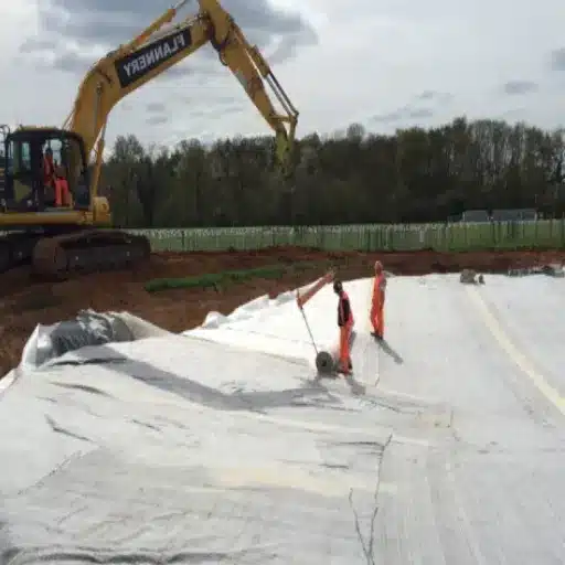
Most GCL failures are installation failures wearing a material-failure costume. These seven account for the majority.
- Covering late or not at all. The bentonite hydrates unconfined and the seam never recovers.
- Under-lapping. Installing a generic default instead of the governing requirement, missing that ponds need 300 mm with bentonite and film-laminated products need mastic sealing.
- Skipping supplemental bentonite. Overlaps without it leak up to 8 times more.
- Shingling up-grade. Lapping panels against the flow direction, funnelling water into the seam.
- Dragging panels across the subgrade. Abrades the carrier geotextile and disturbs the bentonite.
- Thin cover with uncontrolled traffic. Below roughly 300 mm, heavy plant mobilises bentonite.
- Not inspecting before covering. Once soil is on, the seam and hydration state cannot be verified.
Number seven deserves emphasis. Every other mistake on this list is recoverable at the hold point. After it, the only remedy for a defect is excavation.
QA/QC and CQA Inspection Checklist
This is the part of GCL installation most supplier content omits, and the part that protects the owner.
Pre-installation. Approve the subgrade in writing. Review roll certificates and GRI-GCL-3 or ASTM test reports, inspect every roll and document damage, and hold at least 7% extra material for overlaps and wastage.
During GCL installation. Record the panel layout, including panel numbers, overlaps, and seam coordinates. Measure each overlap dimension before bentonite placement, verify the supplemental bentonite rate, and inspect penetration details as they are built. Run hydration checks on any panel exposed to moisture.
Pre-cover hold point. Perform CQA inspection and obtain written approval before any cover soil is placed. Overlaps, seams, patches, penetrations, and hydration state are all verified here, never after.
Documentation. Daily reports, as-built panel layout, patch and repair log, moisture test results, and a photographic record.
Third-party testing. Bentonite mass per unit area by ASTM D5993, index flux by ASTM D5887, quality control sampling by ASTM D5889, and storage and handling by ASTM D5888.
Retained production samples and test reports shipped with each consignment let a CQA team verify conformance on arrival rather than discovering a shortfall at the hold point.
Application Notes, Cost & Logistics
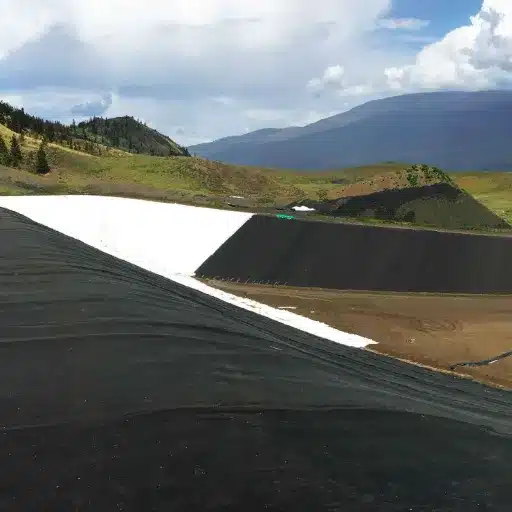
Applications change the emphasis rather than the procedure.
Landfills consume 45 to 50% of global GCL demand and are the most specification-heavy application. Reinforced grades are standard where cell walls are steep, because unreinforced product struggles to meet interface shear demand on a slope. A GCL landfill liner for base and cover systems follows the sequence above with stricter CQA and heavier cover.
Ponds, reservoirs and canals are where the 300 mm longitudinal overlap plus continuous bentonite bead applies, and where supplemental bentonite is required regardless of product.
Mining is the fastest-growing GCL application at a 7.01% CAGR, and the segment where chemistry attacks the barrier hardest. Acidic and hypersaline process solutions load the bentonite with divalent cations and erode swell capacity, so seam integrity matters more here than anywhere else. If you are specifying GCL for mining, treat the chemistry of the contained solution as the first design input.
GCL installation alone runs USD 2 to 4 per square metre, with material plus installation landing between USD 8 and 12 per square metre. GCL installation typically represents 30 to 50% of total project cost, which makes this procedure a cost document as much as a technical one. Against compacted clay, the same 10,000 square metre barrier takes roughly 2.4 times the man-hours.
That cost advantage is real and fragile. A project manager named Daniel learned this on a 4,800 m² reservoir job. His crew laid 1,200 m² late on a Friday and left it uncovered. Weekend rain pushed moisture readings to roughly 50% across the exposed section, and replacing it cost more than the labour saving that caused the delay.
GCL Installation: Frequently Asked Questions
What overlap do GCL panels need?
A minimum of 150 mm longitudinally and 500 mm end-of-roll per ASTM D6102. Pond applications typically require 300 mm plus supplemental bentonite, and film-laminated products need 100 mm with mastic.
Which direction should GCL panels be shingled?
In the direction of grade, so water flows over the seam rather than into it. On a floor, the upgradient panel laps over the downgradient panel.
Can you install a GCL in the rain?
No. Premature unconfined hydration damages the seal, and overlaps are the most vulnerable zone. If rain interrupts work, cover deployed panels with plastic sheeting immediately.
How thick should cover soil be over a GCL?
At least 300 mm of approved cover soil to provide confining stress, rising to 600 mm where construction traffic is heavy.
How do you know if a GCL has hydrated prematurely?
Soft zones and lasting footprints when you walk the panel, an indiscernible granular structure in a cut sample, and ASTM D2216 moisture readings. Background panels have read around 20% against roughly 50% in hydrated areas. Replace above 40% bentonite moisture.
How do you repair a damaged GCL?
Cut a full GCL patch with at least 300 mm of overlap on all sides and apply granular bentonite at roughly 0.4 kg per linear metre. A geotextile-only patch is acceptable only where the bentonite core is undisturbed.
Conclusion
GCL installation is not complicated, but it is unforgiving. The dimensions are simple, the tolerances are tight, and the failure modes stay silent until water finds them.
Five rules carry most of the weight. Keep dimensional discipline at 150 mm longitudinally and 500 mm end-of-roll, and let the stricter governing requirement win. Treat supplemental bentonite as a structural component rather than an optional extra. Control hydration obsessively, because unconfined swelling cannot be repaired in place. Cover the same day with at least 300 mm of soil and keep plant off the liner. And hold the pre-cover CQA inspection as a genuine stop-work point, not a formality.
Do those five things and a certified GCL will deliver certified performance. Skip them and the certificate becomes a document about a product that never existed on your site.
Ready to specify with confidence? Request a technical quote from our engineering team for roll configurations, ASTM test reports, retained samples, and project-specific installation guidance, including flexible order quantities for pilot and mid-scale projects.