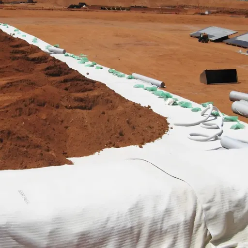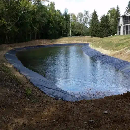
Geogrid installation follows a seven-step field protocol: prepare the subgrade, lay a separator if specified, unroll the geogrid in the correct orientation, pull it taut and pin it, overlap seams to the right width for the soil, place a minimum 150 mm (6 in) aggregate cover, and compact in thin lifts. When done correctly, the grid mobilizes its design strength and the reinforced layer performs as engineered. When done poorly, most failures trace back to the installation, not the material.
Ask the contractor who learned that the hard way. In 2023, a site crew in Texas installed a uniaxial geogrid on a 4 m retaining wall with the strong direction running parallel to the wall face instead of perpendicular. The mistake cut the grid’s effective strength by roughly 70%. Within eight months the facing bulged, the wall had to be demolished, and the rebuild cost more than double the original wall. The geogrid itself was never the problem. The orientation was.
That story repeats on roads, slopes, and soft-ground platforms worldwide. The geogrid performs; the installation does not. This guide gives you the complete installation protocol with the numbers you need: overlap by subgrade CBR, cover thickness, anchor spacing, and the seven mistakes that cause most failures. Whether you are a contractor, an engineer, or a procurement buyer evaluating total installed cost, you will finish with a clear field checklist.
Key Takeaways
- Geogrid installation is a seven-step process, and correct orientation is the single most important step; a misplaced strong direction can cut effective strength by up to 70%.
- Overlap seams by subgrade support: 300 mm on firm ground, 500 to 600 mm on soft ground, and 750 to 900 mm on very soft ground.
- Never drive construction equipment directly on exposed geogrid; place a minimum 150 mm (6 in) aggregate cover first.
- Most documented geogrid failures are installation errors, which is why a pre-cover QA/QC inspection with the design engineer prevents the costliest mistakes.
- A quality geogrid supplier provides installation guidance and test data, which is why specification and QC matter as much as the material price.
How to Install Geogrid: The 7-Step Process
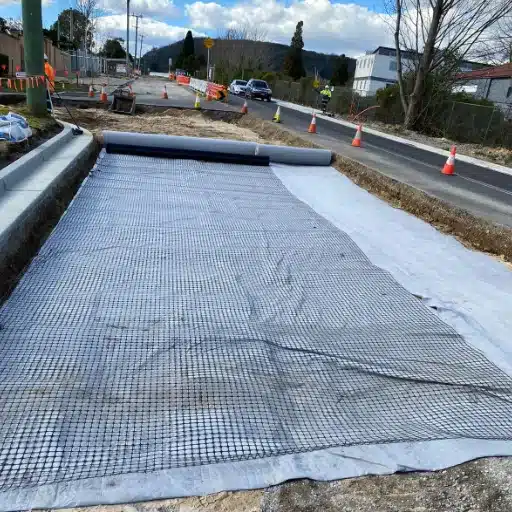
Every geogrid installation, regardless of application, follows the same sequence. The exact dimensions change with soil and load, but the order does not.
- Prepare the subgrade. Clear vegetation, topsoil, stumps, and debris. Grade to design elevation, compact, and proof-roll. Fix soft spots before you place a single panel.
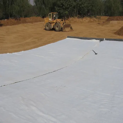
- Lay a geotextile separator first, if specified. On fine-grained or soft subgrades (CBR 4 or less), a separator stops fines from pumping up into the aggregate. The geogrid goes immediately on top.
- Unroll in the correct orientation. Check the machine direction (MD) and transverse direction (TD) markings on the roll. For uniaxial geogrid, the strong direction must face the primary load. On slopes, the main stress direction runs down the slope.
- Pull taut and pin. Remove wrinkles and slack by hand. Anchor the start of the roll at the center and corners, then pin edges every 5 to 10 ft on flat ground and every 3 to 5 ft on slopes.
- Overlap and seam by subgrade. Overlap 300 mm on firm ground, more on soft ground. Stagger panel ends so seams do not line up, and shingle overlaps in the direction the fill will be spread.
- Place the initial cover. Spread at least 150 mm (6 in) of aggregate before any equipment crosses the grid. Heavier plant and very soft subgrades need more, typically 200 to 300 mm.
- Compact in thin lifts. Build the base in 150 to 200 mm lifts to 90 to 95% Standard Proctor density. On soft, fine-grained soils, use static compaction first instead of vibratory.
That is the whole protocol in one breath. The rest of this guide explains why each step matters and how to get the numbers right for your project.
Site Preparation & Subgrade Requirements
A geogrid cannot fix a poorly prepared subgrade. It reinforces what is beneath it, so the subgrade must be a stable platform first.
Start by stripping vegetation and topsoil, then excavate to the design subgrade elevation. Remove sharp objects, roots, and debris that could puncture the grid. Grade the surface smooth and level, and crown it so water drains away from the work zone. Standing water softens the soil and reduces the friction the grid relies on.
Compaction and proof-rolling reveal the weak spots. Compact the subgrade to the specified density, then run a loaded proof roll and watch for pumping or rutting. Undercut soft pockets and replace them with compacted granular fill before placing the grid. Do not simply lay geogrid over a known soft area and hope it spreads the load; on very soft ground the approach is different and more involved.
California Bearing Ratio (CBR) is the number that drives most installation decisions, including whether geogrid reinforcement is required. The U.S. Army Corps of Engineers guidance in ETL-1110-1-189 uses CBR to separate subgrade categories:
| Subgrade condition | Typical CBR | What to do |
|---|---|---|
| Very soft | Less than 0.5 | Design a construction platform; staged fill required |
| Soft | 0.5 to 4 | Stabilization plus reinforcement; add a geotextile separator on fine-grained soils |
| Firm | Greater than 4 | Design normally; the geogrid provides reinforcement credit |
On very soft ground (CBR below 0.5 to 1), you may lay the geogrid directly on the surface after removing major protrusions and filling local hollows. Do not over-disturb the surface crust, because the crust provides some support. This is the domain of geogrid for soft ground and subgrade stabilization, where the rules for cover, overlap, and staged fill are more demanding.
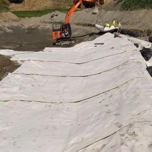
A separator matters more than many teams realize. On silts and clays, water softens the fine soil and it works upward into the aggregate. A nonwoven geotextile stops that migration while the geogrid above it carries the tensile load. When the plan calls for a separator, place it first with seams overlapped about 300 mm and pinned, then place the geogrid immediately on top so the two layers work together.
Geogrid Orientation: Getting the Strong Direction Right
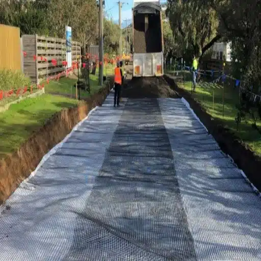
Orientation errors cause more field failures than any other single mistake. A uniaxial geogrid is strong in one direction and much weaker in the other, and installing it backward neutralizes the reinforcement.
Every roll is marked with a machine direction (MD) and a transverse direction (TD). The MD is the strong direction for uniaxial geogrid, which is used for retaining walls, slopes, and embankments. The rules are simple:
- Retaining and MSE walls: the strong (MD) direction must run perpendicular to the wall face, extending back into the retained soil. Installed parallel instead, effective strength can drop by up to 70%.
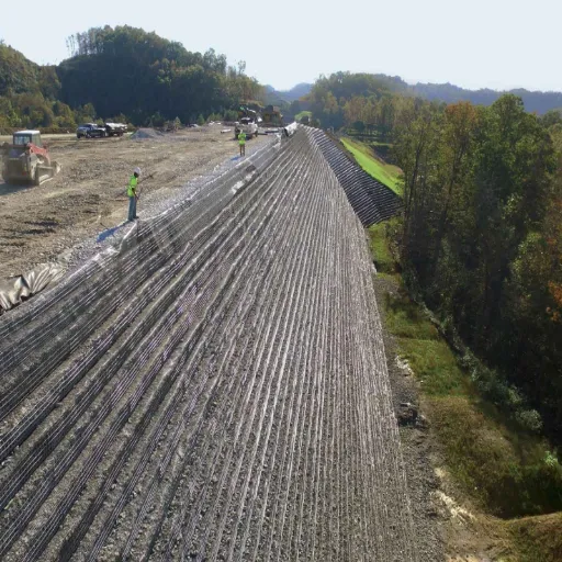
- Slopes: the main stress direction runs down the slope. Never overlap the grid in the main stress direction; use one continuous panel from crest to toe where the design requires it.
- Road bases and driveways: biaxial geogrid has balanced strength in two directions, so orientation is less sensitive. Unroll it perpendicular to traffic direction for the best load distribution.
- Triaxial geogrid: the triangular apertures spread load in all directions, but still verify the orientation against the plan.
Check the MD and TD markings before you unroll, and confirm the orientation against the design drawings. It takes thirty seconds to check and months to fix. For the full reference on uniaxial, biaxial, and triaxial behavior, see the complete geogrid guide to types, applications, and selection.
Geogrid Overlap & Seaming Requirements
Overlaps are where load transfers between panels, and short overlaps are a common field failure. The overlap width depends on the support the subgrade provides, so match it to the soil, not to a habit.
| Subgrade support | Typical CBR | Overlap |
|---|---|---|
| Firm | Greater than 8 | 300 mm (12 in) |
| Medium | 4 to 8 | 300 to 500 mm |
| Soft | 1 to 4 | 500 to 600 mm |
| Very soft | Less than 1 | 750 to 900 mm |
Manufacturers set similar floors. Tensar specifies a minimum 300 mm overlap for its H-Series geogrids, and Secugrid’s installation guide does the same, with wider laps on weaker ground. Overlap less than that and the panels cannot transfer load across the seam.
Three rules keep overlaps working:
- Shingle in the direction of fill. Lay each successive panel so the trailing edge sits on top of the previous panel, the way roof shingles overlap. Fill spreading then tends to close the seam rather than open it.
- Stagger the panel ends. Do not let the seams line up in a straight row across the site. Aligned seams create stress concentrations and visible dips after compaction. Offset adjacent panel ends by at least 500 mm.
- Secure the overlaps. Hold laps down with small piles of aggregate or pins before filling. Loose overlaps shift under the first truck passes and open up.
Some systems do not overlap at all. Wrapped-face slope construction and certain wall systems specify butt joints or mechanical connections with cable ties or hog rings. Follow the design drawings; when the plan specifies a connection method, use it rather than defaulting to an overlap.
Anchoring & Tensioning the Geogrid
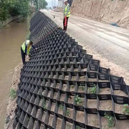
A geogrid only reinforces when it is held taut. Slack in the grid reduces interlock efficiency, inhibits load transfer, and leads to uneven settlement. Tensioning and anchoring are not optional details.
Pull the grid taut by hand as you unroll it, working out the wrinkles before you pin. Anchor the start of the roll at the center and at the corners before unrolling fully. Then work down the edges and pin as you go.
Standard anchor methods:
- U-staples driven through the apertures. Large-gauge staples suit most applications and are the most common field method.
- Washer-and-pin systems, which hold the ribs down without cutting the polymer.
- Small piles of aggregate over the overlaps and at the ends, which hold the grid in place and protect the edge.
Spacing depends on the ground. Pin every 5 to 10 ft on flat, stable areas, and tighten the spacing to every 3 to 5 ft on slopes, curves, and other areas where the grid is more likely to shift. Add extra pins at overlaps and at cut ends.
Two cautions from experienced crews. First, do not over-restrict the grid with excessive stakes; over-pinning can create wrinkles and voids between the grid and the soil. Tension, then anchor, is the order. Second, certain stiff grids have a memory effect and roll back up the moment you cut them. Pin or weight the cut ends immediately, or the panel will snap back before you can cover it.
Cover Thickness & Construction Traffic Rules
Can you drive on geogrid? No. Never allow construction traffic directly on exposed geogrid. Driving on the bare grid tears it, displaces panels, and destroys the interlock the design depends on.
The rule is to place a minimum 150 mm (6 in) of aggregate cover before any equipment crosses the grid. Heavier plant needs more, typically 200 to 300 mm, and very soft subgrades require the thickest cover of all. Some manufacturers quote 4 to 6 in for light traffic and 8 to 12 in for heavy equipment; the principle is the same, protect the grid before you load it.
How you place the fill matters as much as how much you place:
- Dump onto placed fill, not onto the grid. Back-dump aggregate so it cascades onto the grid from a small height. Dropping a bucketload from height shifts the panel and folds it.
- Keep equipment speeds under 5 mph. Avoid sharp turns and sudden stops, which drag the aggregate and shear the grid.
- Use low-ground-pressure equipment on soft ground, and prefer static compaction over vibratory on silts and fine-grained soils where vibration can damage the interface.
- Respect the UV window. Cover exposed geogrid within 24 to 48 hours. Grids with at least 2% carbon black tolerate longer, often 7 to 15 days, but never exceed the manufacturer’s exposure limit.
Want to see how this plays out on a real road project? Our geogrid for road base and driveway stabilization guide walks through the thickness charts and aggregate savings step by step.
Application-Specific Geogrid Installation
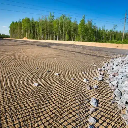
The seven-step process is the same everywhere, but each application adjusts the details. Here is how the protocol changes on the three most common jobs.
Road Bases & Driveways
Unroll biaxial geogrid perpendicular to traffic direction. Place a 150 to 200 mm initial lift, then compact in 150 to 200 mm lifts to at least 95% Standard Proctor. Use angular, well-graded crushed stone; rounded pea gravel does not interlock with the apertures and defeats the reinforcement. The full road-base design and thickness guidance lives in our geogrid for road base guide.
Retaining & MSE Walls
Place the first geogrid layer after the base course is complete, with the grid edge against the back of the facing blocks. Backfill in 200 mm (8 in) lifts and compact with a plate compactor, minimum two passes, working from the facing back toward the excavation. Never compact directly on the grid. Keep the uniaxial strong direction perpendicular to the wall face and hold tension while placing the first six inches of backfill.
Slopes & Embankments
Cut benches or steps into the slope to hold the grid, and anchor the crest. Lay continuous panels down the slope in the main stress direction, wrap the grid at the slope face or integrate it with a facing system, and place at least 150 mm of soil cover over the top layer before compaction equipment passes. Manage drainage with a toe drain and surface water cut-off.
For retaining walls, the embedment length typically runs 0.7 to 1.0 times the wall height. For steep slopes, the design determines the vertical spacing between grid layers, often 0.6 to 3.0 m. These are design decisions; the installation team executes them to the drawings.
QA/QC & Inspection Checklist
The most documented geogrid failures occur when neither the design engineer nor a construction quality assurance (CQA) inspector is on site during installation. A simple pre-cover inspection catches nearly every costly error.
Run this checklist before any aggregate goes down:
- Verify the delivered rolls match the specified type and grade, and request test certificates. Confirm tensile values meet the geogrid specifications and ASTM standards, junction efficiency is 90% or better, and carbon black content is adequate for UV exposure.
- Inspect during unrolling. Cut out damaged areas over the full width and repair or replace them as directed. Log every repair in the field report.
- Confirm orientation against the drawings, checking MD/TD markings on each roll.
- Check tensioning. The grid should be taut with no wrinkles and no visible slack.
- Measure the overlaps. Confirm lap width against the CBR table, and verify seams are staggered and shingled correctly.
- Verify anchoring at the specified spacing, including edges, overlaps, and cut ends.
- Check cover thickness before any equipment traffic, and document compaction densities at 90 to 95% Standard Proctor.
Hold the inspection as a formal step, not a formality. When the crew knows the engineer will walk the grid before cover, the mistakes that cause failures simply stop happening. For the full deep-dive on tensile strength, long-term design strength, and test methods, our geogrid specifications and ASTM standards reference covers the details.
7 Common Geogrid Installation Mistakes
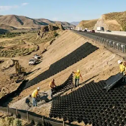
Here are the seven failures that show up again and again on geogrid projects, each paired with the fix.
- Wrong orientation. Uniaxial strong direction parallel to the wall face instead of perpendicular; strength cut by up to 70%. Fix: check MD/TD before every unroll.
- Aligned seams. Panel ends lined up in a row, creating stress concentrations and visible dips. Fix: stagger seams by at least 500 mm.
- Short overlaps. Laps under 300 mm that cannot transfer load. Fix: use the CBR overlap table, not a guess.
- Slack, untensioned grid. Wrinkles and loose panels that never mobilize interlock. Fix: pull taut, then anchor.
- Driving on exposed geogrid. Equipment tears and displaces the bare grid. Fix: minimum 150 mm cover before traffic.
- Dumping fill from height. Impact shifts panels and folds the grid. Fix: back-dump onto placed fill and spread gently.
- Thick lifts and wrong backfill. Over-thick lifts leave loose material at the grid, and rounded aggregate cannot interlock. Fix: compact in 150 to 200 mm lifts with angular, well-graded stone.
A contractor who fixes these seven things eliminates the bulk of geogrid field failures. If you are seeing rutting, bulging, or settlement on a reinforced project, run this list before blaming the material.
Frequently Asked Questions
How do you install geogrid?
Prepare and compact the subgrade, unroll the geogrid in the correct orientation, pull it taut, pin the edges, overlap seams by the CBR-based width, place a minimum 150 mm aggregate cover, and compact in thin lifts.
Can you drive on geogrid?
No. Construction traffic must never run directly on exposed geogrid. Place a minimum 150 mm (6 in) of aggregate cover first, and more for heavy equipment or very soft subgrades.
How much overlap do geogrids need?
Overlap 300 mm on firm ground (CBR above 8), 300 to 500 mm on medium ground, 500 to 600 mm on soft ground, and 750 to 900 mm on very soft ground. Stagger the seams and shingle them in the direction of fill.
How much gravel do you need over geogrid?
At least 150 mm (6 in) of compacted aggregate above the grid before any equipment traffic. Heavy plant and very soft subgrades need 200 to 300 mm.
Do you need a geotextile under geogrid?
On fine-grained or soft subgrades with a CBR of 4 or less, a geotextile separator stops fines from pumping up into the aggregate. Place the separator first, then the geogrid immediately on top.
How long can geogrid be left exposed?
Cover exposed geogrid within 24 to 48 hours. Grids with at least 2% carbon black can tolerate up to about 7 to 15 days, but never exceed the manufacturer’s exposure limit.
Conclusion
Geogrid installation is a discipline, and every step earns its place. Correct orientation mobilizes the full design strength. Taut, anchored panels transfer load seam to seam. CBR-matched overlaps keep the grid continuous. A minimum 150 mm cover protects the reinforcement from the very equipment that will rely on it, and thin-lift compaction locks the aggregate into the apertures. Add a pre-cover QA/QC inspection and the seven common mistakes become preventable instead of predictable.
The payoff is real. Correctly installed geogrid reduces base course thickness, extends pavement life, and holds walls and slopes in place for decades. The material does the work, but only the installation lets it.
When you specify geogrid for your next project, ask for the numbers: tensile strength at 2% and 5% strain, junction efficiency, carbon black content, and the manufacturer’s overlap and cover guidance. A supplier that provides test data and installation support is worth more than a low price. At Shanxi Shengxing, we supply export-ready geogrids for road and earthworks reinforcement, with technical consultation and flexible order quantities for projects of every size.
Request a technical quote today, and our engineering team will help you match the right geogrid to your installation plan. Contact engineering support to get started.