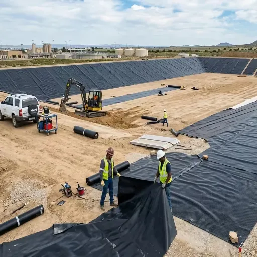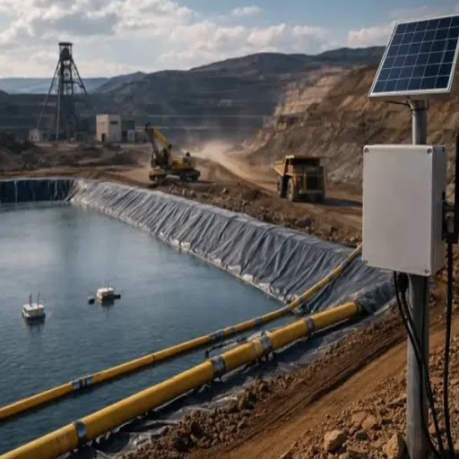
Electrical leak location site preparation starts with the barrier to be tested. Check its electrical path, liner contact and isolation. Then prepare the surface and access before the crew arrives.
Record who accepts each condition and what remains on hold. A booked survey date alone does not make the liner ready.
The hard part is the handoff between crews. One team sees finished earthworks; another needs proof that the test circuit can work. This checklist helps owners, contractors and construction quality assurance (CQA) staff bridge that gap.
Illustrative scenario A: A crew has an appointment, but the section drawing omits the layer beneath the geomembrane. Ask the survey specialist to review that layer and its connection. Do not assume that a smooth surface proves readiness.
Key Takeaways
- Identify the exact barrier, area and construction stage to be surveyed.
- Check conductivity, local contact and boundary isolation as separate conditions.
- Match cleaning, moisture and water support to the selected method.
- Give each open item an owner, remedy and recheck record.
- Keep preparation release separate from survey results and final acceptance.
Electrical Leak Location Site Preparation: Scope and Owners
Confirm the barrier and construction stage
Start with the current drawing and a marked zone plan. Identify which barrier will be tested, whether it will be exposed or covered, and the proposed method. State how the site will look at the time of testing. Check that this matches the work schedule.
Electrical leak location (ELL) uses an electrical response to locate breaches under suitable conditions. For method selection, see our geomembrane electrical leak location method guide. Use this checklist once the team has chosen a proposed method. It does not choose an instrument or replace the provider’s procedure.
Ask the provider to check that the method suits the installed system. Then agree the site work needed.
Use HDPE geomembrane information to identify material questions and the page’s inquiry route for missing product details. Bring the actual liner and backing information to the survey specialist. Ask the supplier to confirm the material. Leave survey approval with the qualified project team.
Mark what the visit will cover: floor, slopes, sumps, pipe details and areas awaiting other work. If cover placement will follow, show that sequence on the same record. A survey describes the liner at the time of the test. It cannot prove the state of the liner after later work.
Assign actions before the joint walkdown
The following roles are a suggested coordination framework. Assign them through the project contracts and quality plan. They are not universal legal duties.
| Suggested role | Readiness contribution |
|---|---|
| Owner or representative | Agrees scope, exclusions and release authority |
| Installer | Supplies liner details, repair status and access constraints |
| Main contractor | Coordinates traffic, utilities and other work |
| CQA representative | Tracks evidence, open items and the handoff record |
| Survey provider | Confirms method-specific conditions and capability checks |
Circulate the record before the walkdown. Ask each person what they can confirm and which decisions they need from others. Compare the proposed release date with the geomembrane installation sequence. Resolve conflicts before crews work to different assumptions.
Check the Conductive Path and Contact Through the Liner System
Trace the intended path on the section drawing
A material label does not establish a usable test circuit. Show the survey provider the layers around the target barrier. Note their state and the planned return connection. Mark those features on the drawing and identify where the team can check them in the field.
Check three things: current flow, local contact and the return path. Can current flow through the layer in its planned state? Does that layer touch the liner where a hole might occur?
Then ask whether the path leads back to the test equipment. Each check needs its own answer. A moist layer with poor contact may leave a question unresolved.
The public guidance in ASTM D7909 explains why local contact and electrical isolation matter to a capability check. The linked page is a historical edition listing that points to a later reapproval. Use the edition required by the project and the applicable procedure for actual field work.
List the subgrade or lower layer, any conductive backing, the protective layers and drainage spaces. Note where the drawing differs from the installed build-up. A change to a specified layer can affect the test circuit. Send it to the provider and record the agreed next step.
Flag uncertain contact and double-lined details
Wrinkles, bridging and dry layers deserve their own observations. Can the chosen method work in those local conditions? A product name cannot answer that question. A conductive backing does not remove the need to review access, isolation and the method’s other conditions.
Illustrative scenario B: The drawing shows two liners with a drainage space between them. The team plans to test the upper barrier. They have not checked its return path through those layers.
Record the gap in the plan and ask the provider to review it. Do not turn a general article into permission to flood the drainage space or alter the design.
Use a row such as: “Upper liner return path unresolved; drawing revision attached; survey provider to review; area on hold.” That row names a decision. It makes no claim about a leak, liner failure or test result.
Request written confirmation of the agreed arrangement and the evidence still needed at mobilization. If a check must wait until the crew arrives, state that in the record. Don’t close the row merely because a drawing has been emailed; close it when the responsible person records the decision and its limits.
Inspect Perimeter Isolation and Penetration Bypasses
Walk the boundary and mark possible bridges
Electrical isolation helps keep current on the intended test path. A conductive bridge around the liner can let current take a different route. Inspect the actual perimeter and details with the provider’s requirements in hand, rather than accepting the boundary line on a drawing as proof of isolation.
Look for soil bridging the test boundary, water connecting areas that should be separate, and details at pipes or structural attachments. Treat battens, metalwork and penetrations as review locations. Their effect depends on the test circuit. Seeing an object alone does not prove that the survey is invalid or the liner has failed.
Solmax’s technical note on ELL preparation discusses perimeter isolation, water support and liner-system details. Its example arrangements should not become universal construction dimensions. Have the provider review the required isolation for this site and method.
Give each potential bridge a location on the zone plan. Use a photo to show the location. Use a drawing to show the detail around it.
Neither replaces the provider’s assessment of the electrical path. Keep the decision with the image so the next crew knows what was agreed.
Agree a remedy without damaging another function
Do not copy a fixed isolation-gap width from another project. State the required condition in the approved procedure and record who will verify it. If excavation or a detail change is proposed, route it through the relevant design and construction approvals before work begins.
Isolation for a survey is not permission to disconnect protective electrical grounds or compromise structural restraints. The remedy must keep the site safe and protect the liner. Assign the work to the responsible team, with a recheck by the agreed reviewer.
In illustrative scenario B, a possible perimeter bridge becomes a separate row from the uncertain lower return path. Resolving one does not automatically resolve the other. This distinction prevents a single photograph or verbal assurance from closing unrelated preparation issues.
For every boundary row, retain the observation, location, evidence, responsible role, proposed remedy and recheck name/date. Use “review” while a design or provider decision is pending. Use “hold” when the team has identified an unmet condition that prevents release of the affected area.
Match Surface, Water and Weather Conditions to the Agreed Method
Confirm cleaning and support resources
There is no universal instruction to make every liner wet or dry. Different electrical methods need different conditions. Ask the provider to state the required surface condition, cleaning needs and water arrangements in the mobilization plan. Use the procedure for the chosen method and the actual liner.
| Survey condition | Preparation question | Release evidence |
|---|---|---|
| Exposed method needing a dry surface | Is the surface clean and dry as required? | Provider’s agreed check at the work area |
| Water-based exposed method | Can water and hose support reach the planned area? | Supply and support arrangements confirmed |
| Covered survey | Do the cover and lower layers support the intended path? | Agreed field checks and limitations recorded |
For water-based work, name who supplies water, where it is available and how hoses will reach the area. Confirm any assistance the provider needs. A water source at the site gate does not establish support at the far slope or sump; discuss those locations during the walkdown.
For covered areas, record the cover type and its planned state. Avoid adding a universal moisture percentage or maximum cover depth to the checklist. Use numbers only when the project procedure and site evidence support them.
Define what happens when conditions change
Illustrative scenario C: Rain arrives after an exposed area has been prepared for a method that requires a dry surface. The record now describes yesterday’s condition. The team asks the provider whether to wait, prepare again or revise the plan through the agreed process; the example implies no survey outcome.
Review the plan again if cover, drainage or other work changes the area. Record what changed and which zones it affects. Keep other released zones separate if the provider and project team can justify that distinction.
The public scope of ASTM D8265-26 covers installations with cover materials. It addresses site conditions and the need to record nonideal conditions. This supports documenting limits, not claiming that any damp cover is testable. Keep the actual checks and any accepted limitations with the readiness record.
Before discussing test compatibility, compare the installed specification with the available geomembrane material options. If the product identity is unclear, use the material inquiry route to resolve it. Don’t replace an unknown backing or layer with a guessed specification.
Prepare Safe Access, Utilities and the Construction Handoff
Confirm reach and exclusions
A reachable floor does not prove that every slope and detail is reachable. Ask the survey team to check how they will reach sumps, corners, pipe details and transitions. Record where equipment, hoses and personnel can go under the site’s work procedure and where another arrangement is needed.
Site-specific safety planning belongs with qualified personnel. Before the crew arrives, agree how to manage electrical equipment, water, slopes and other site hazards. This checklist does not supply voltage settings, entry procedures or instructions for improvised testing. Record the approved procedure and the person responsible for briefing the crews.
List practical support separately: water, hose routing, agreed utilities, access routes, helpers and repair-team availability. Name who supplies each item and when it is needed. “Contractor to assist” is too broad if the provider needs a named person at a particular work area.
If a zone cannot be reached, mark it explicitly. State whether it is excluded, awaiting another access arrangement or still on hold. Avoid using “whole area ready” when a sump or slope remains unresolved. The scope map should let a person who missed the meeting understand the boundary.
Protect the released construction state
Agree how other work will be controlled after preparation and during the survey. Identify who can release construction traffic and how later cover work or repairs will be reported. For the handoff to work, crews must know what site state to preserve.
Continuing illustrative scenario C, the rain issue is resolved for the planned work, but a cover crew then enters one zone. That new activity needs a fresh review of the affected area. A previous readiness signature does not establish its condition after the work.
Solmax’s 18 August 2026 discussion of early leak-check planning reinforces the value of planning leak checks early. Apply that lesson to the schedule: discuss access and survey stage before later construction removes an opportunity. It is a planning point, not a new regulatory deadline or a guarantee of detection.
For the walkdown, carry the zone plan, open-item list and current construction schedule together. Name the person who will resolve any conflict between them. Keep the agreed follow-up visible to the installer, CQA staff and survey team.
Release the Area Only With Capability Checks and Open Items Recorded
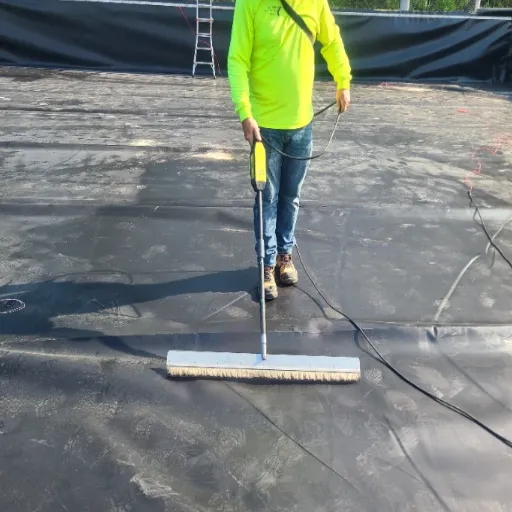
Agree the demonstration and repair responsibilities
Before release, ask how the provider will demonstrate capability under the actual conditions. Agree what proof to keep. State how a failed or limited check will change the work plan. A check in one place does not prove contact and isolation in every other zone.
ASTM D7909 discusses intentional defects used for capability assessment and the need for agreement and documentation. Do not make a hole as an informal preparation task. The owner must agree to such work. Qualified staff must plan it and assign the repairs and follow-up checks.
Keep ELL readiness separate from geomembrane welding and seam checks. Electrical response and weld strength answer different questions. Keep seam and repair records in the project quality file. A booked survey or signed checklist cannot replace them.
Use a ready, hold or review decision
Use this original coordination worksheet alongside the approved project procedure. It is a handoff aid, not an ASTM form or final survey certificate. Use a separate row for each zone or detail that needs review.
| Item | Evidence to attach | Suggested reviewer | Hold or review trigger |
|---|---|---|---|
| Scope and barrier | Zone plan and drawing revision | Owner/provider | Barrier or stage unclear |
| Path and contact | Layer details and agreed field checks | Provider | Return path unresolved |
| Isolation | Boundary/detail observations | Provider/contractor | Potential bypass not assessed |
| Surface and water | Condition check and supply plan | Provider/contractor | Required condition unmet |
| Access and later work | Access map and work controls | Contractor/CQA | Zone unreachable or changed |
| Capability and repairs | Agreed checks and repair responsibility | Provider/owner/CQA | Check or follow-up unresolved |
Add fields for status, corrective action, action owner, recheck name/date and remaining limitations to every row. “Ready” means the assigned reviewer accepts preparation for the stated scope. “Hold” means an unmet requirement prevents release. “Review” means a decision is still needed; it is not permission to proceed.
Close illustrative scenario A by attaching the clarified drawing and the provider’s decision. That resolves the missing-information row only. The survey still needs to take place under the recorded conditions. Its report must show the area tested and the parts left out.
Questions About Electrical Leak Location Site Preparation
Who prepares the area before an electrical leak survey?
Agree responsibilities in the project quality plan and contracts. The contractor and installer can provide access, construction details and support resources, while the survey provider confirms method-specific needs. The owner and CQA team should know who accepts each item. Give every unresolved condition an action owner and a recheck date.
Should the geomembrane be wet or dry for the survey?
Follow the selected method’s procedure. Water-based exposed surveys need planned water support, while other exposed methods require a dry surface. Covered surveys need suitable conditions through the surrounding layers. Ask the provider to confirm the required state; adding water without review can conflict with the planned method or liner-system design.
How wide should an isolation gap be?
Use the provider-reviewed project detail rather than a universal width. The purpose is to prevent competing conductive paths around the target barrier while preserving safety and the liner design. Record the required condition, who will establish it and how it will be rechecked. A dimension copied from another site proves none of these.
Does a damp GCL prove the test will work?
No. A damp geosynthetic clay liner does not prove good local contact. It does not prove continuity or a suitable return path either.
Review the installed layers and the proposed method together. Ask the provider what field evidence is needed. Keep the area on hold if an essential path or contact condition remains unresolved.
What changes require another readiness review?
Review changes that may affect the agreed survey conditions: rain, cover placement, traffic, repairs, altered boundaries or restricted access. Identify the affected zones and ask the responsible reviewer whether preparation or capability checks need repeating. Keep the new decision with the first record. Don’t assume an earlier signature covers later work.
Take the completed checklist, drawings and open-item list to the joint walkdown. For missing liner or backing details, start with the HDPE material information and inquiry route, then give the confirmed information to your survey specialist. Release a defined area for a defined test condition; record the survey’s findings separately.