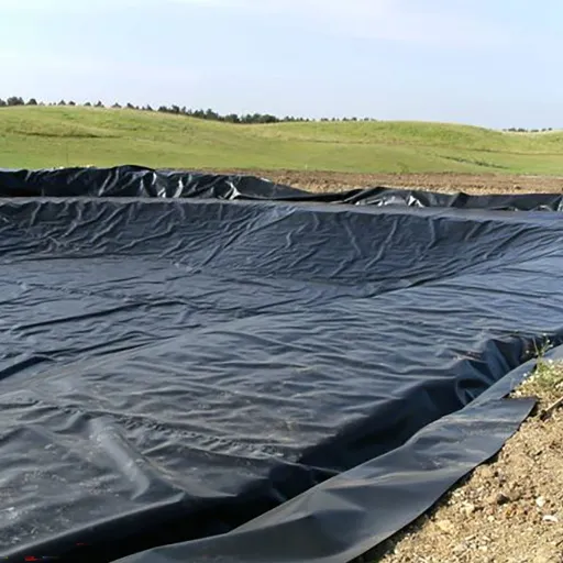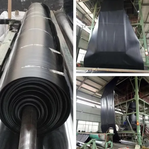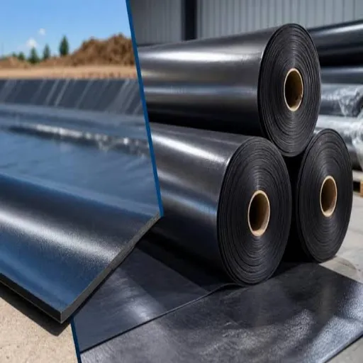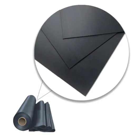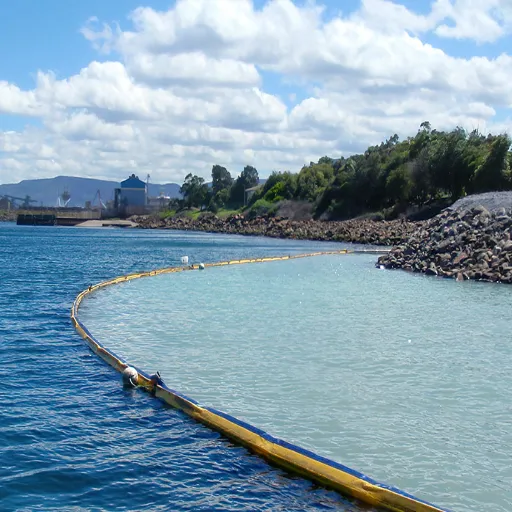
LLDPE geomembrane thickness runs from 0.50 mm to 3.00 mm under GRI-GM17. For most containment work the answer is 1.50 mm for an exposed pond, lagoon or reservoir, 1.00 mm for a protected installation or a factory-welded tank, and 0.50 to 0.75 mm only for light duty over a prepared base.
Two suppliers can both quote “1.5 mm LLDPE” and ship different amounts of polymer. One datasheet means nominal thickness; the other means the lowest reading GM17 permits. That gap is where most LLDPE liner thickness arguments start.
The LLDPE geomembrane guide covers material selection. This page covers the gauge: what each step of it buys, and how to write it into a purchase order.
Key Takeaways
- GRI-GM17 covers 0.50 mm to 3.00 mm (20 to 120 mil) in smooth and textured sheet, with a formulated density cap of 0.939 g/cm³ at every gauge.
- Every index property scales almost linearly. Each 0.25 mm adds about 6.5 N/mm of break strength and about 60 N of puncture resistance.
- Smooth sheet may sit 10% below nominal at any single reading. Textured sheet may average 5% below, hit 10% below on two readings in ten, and 15% below once.
- 40 CFR 258.40 sets a 30-mil (0.75 mm) floor for a landfill composite liner and 60 mil where the membrane is HDPE. It’s a minimum, not an endorsement of 0.75 mm LLDPE in a waste cell.
- Published precedent is firmer than the regulation: 1.50 mm for ponds and 1.00 mm for factory-welded tanks in New Zealand’s effluent pond practice note.
LLDPE Geomembrane Thickness: The Short Answer
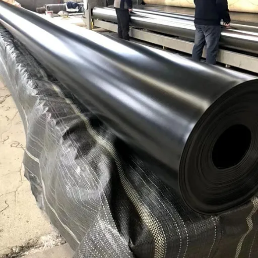
These gauges are starting points, not a design. No table replaces one.
| Typical situation | Starting gauge | Reasoning |
|---|---|---|
| Small features, trays, secondary containment over a smooth base | 0.50 to 0.75 mm | Low consequence, protected, short exposure |
| Farm ponds, irrigation canals, factory-welded tanks | 1.00 mm | Moderate load, welded under controlled conditions |
| Exposed ponds, effluent lagoons, reservoirs, closure caps | 1.50 mm | Sustained UV, thermal movement, higher cost of a leak |
| High exposure, settlement risk, coarse subgrade | 2.00 mm | More puncture margin where the base can’t be improved |
| Demanding containment, heavy equipment, aggressive service | 2.50 mm | Maximum practical margin inside the common supply range |
Four inputs decide where a project lands: load, exposure, chemistry and regulation, and geometry.
Specifying a liner this quarter? Send the design head, the subgrade report and the service condition. We’ll return a thickness recommendation with the GM17 values behind it. Request a specification review.
What GRI-GM17 Requires at Each Gauge
GRI-GM17 is the manufacturing quality specification for LLDPE geomembrane. Revision 17, dated 11 June 2025, fixes geomembrane sheet thickness at eight nominal gauges and sets minimum average values for each. It doesn’t say which gauge to use; it says what that gauge must achieve.
| Nominal | Break strength | Elongation at break | Tear | Puncture | 2% modulus (max) |
|---|---|---|---|---|---|
| 0.50 mm (20 mil) | 13 N/mm | 800% | 50 N | 120 N | 414 MPa |
| 0.75 mm (30 mil) | 20 N/mm | 800% | 70 N | 190 N | 414 MPa |
| 1.00 mm (40 mil) | 27 N/mm | 800% | 100 N | 250 N | 414 MPa |
| 1.25 mm (50 mil) | 33 N/mm | 800% | 120 N | 310 N | 414 MPa |
| 1.50 mm (60 mil) | 40 N/mm | 800% | 150 N | 370 N | 414 MPa |
| 2.00 mm (80 mil) | 53 N/mm | 800% | 200 N | 500 N | 414 MPa |
| 2.50 mm (100 mil) | 66 N/mm | 800% | 250 N | 620 N | 414 MPa |
| 3.00 mm (120 mil) | 80 N/mm | 800% | 300 N | 750 N | 414 MPa |
Elongation holds at 800% and the modulus cap at 414 MPa at every gauge, as the LLDPE geomembrane specifications set out. The values that scale are the ones that resist damage.
What One Step of Thickness Actually Buys
Divide each column by its gauge and the pattern is almost perfectly linear. Break strength sits between 26.0 and 27.0 N/mm for every millimetre of thickness, and puncture between 240 and 253 N per millimetre.
Each 0.25 mm adds about 6.5 N/mm of break strength and about 60 N of puncture. 1.00 to 1.50 mm adds 13 N/mm and 120 N.
Thickness is bought by weight. At about 0.93 g/cm³ a square metre carries roughly 0.93 kg per millimetre: 1.40 kg at 1.50 mm, 1.86 kg at 2.00 mm. The LLDPE geomembrane price article shows what that mass does to cost.
Where 1.25 mm and 2.50 mm Fit
1.25 mm gives a 20% margin over 1.00 mm for a modest weight penalty. 2.50 mm is the practical ceiling for most projects: 620 N of puncture is plenty, and beyond it handling weight and weld difficulty work against the installer.
The LLDPE geomembrane range we supply runs 0.50 mm to 2.50 mm; GM17 specifies to 3.00 mm.
LLDPE Geomembrane Thickness Tolerance: Why 1.5 mm Isn’t Always 1.5 mm
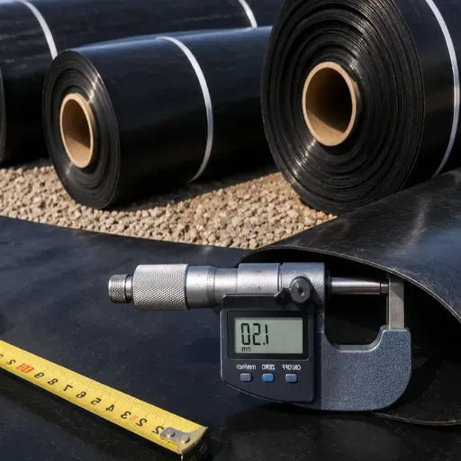
Geomembrane sheet thickness in GM17 is nominal, and the specification tolerates measurement below it. This is the most useful thing to understand before comparing two quotes.
| Surface | Minimum average | 8 of 10 readings | Any single reading | Test method |
|---|---|---|---|---|
| Smooth | Nominal | not specified | −10% | ASTM D5199 |
| Textured (core) | Nominal −5% | −10% | −15% | ASTM D5994 |
| Textured weld edge | not specified | not specified | Nominal −10% | ASTM D5199 modified |
At 1.50 mm the practical floor differs by surface. A smooth sheet must average 1.50 mm, with no single reading under 1.35 mm. A textured sheet must average 1.425 mm, with eight of ten readings at or above 1.35 mm and none under 1.275 mm.
That has a concrete consequence. GM17 sets 370 N of puncture for a smooth 1.50 mm and 300 N for a textured 1.50 mm, and those are minimum lot averages, not readings at the thinnest point. A textured lot may average 1.425 mm, measure 1.275 mm at its thinnest, and still certify at 300 N.
So a contract saying “1.5 mm textured” can be satisfied by a lot whose thinnest points measure 1.275 mm, which is the nominal gauge of a 50-mil sheet. A 4,000 m² reservoir ordered that way arrives with a certificate reporting a lot average of 1.44 mm, a lowest reading of 1.31 mm, and an asperity average of 0.42 mm. Every figure is inside GM17, and the lot still carries less polymer than a smooth order would.
Tomás, a reservoir contractor in central Chile, learned it on a 22,000 m² project. He specified “60 mil textured” and accepted a certificate showing a 1.29 mm core, believing 60 mil was 60 mil. The sheet conformed to GM17 and his order hadn’t distinguished nominal from minimum average, so there was nothing to reject. The renegotiation cost three weeks.
Textured Sheet Carries Less Strength at the Same Gauge
| Property at 1.50 mm | Smooth | Textured | Textured as share of smooth |
|---|---|---|---|
| Break strength | 40 N/mm | 16 N/mm | 40% |
| Elongation at break | 800% | 250% | 31% |
| Tear resistance | 150 N | 150 N | 100% |
| Puncture resistance | 370 N | 300 N | 81% |
| Asperity height | not applicable | 0.40 mm minimum | not applicable |
Tear strength is unchanged. Break strength and elongation aren’t: the texture interrupts the sheet section and is measured to the core between asperities. An engineer comparing the two on one datasheet will conclude the textured product is defective. It isn’t; it’s a different table.
Many projects use both: textured on slopes for friction, smooth on the base for tensile performance. Seaming them together is routine, and the TWI video below shows both.
What Decides LLDPE Geomembrane Thickness
Application gives a starting range. Four inputs move it, and they sometimes pull in opposite directions.
What Presses on the Sheet
Hydraulic head is the input most often blamed for thickness and least often the real cause. Water pressure pushes the liner onto the subgrade; below a few metres, the subgrade carries the load, not the sheet. A liner spanning a void is a different problem, and thickness doesn’t solve it.
The load that matters concentrates. Angular drainage aggregate, a protrusion left in the subgrade, or a soft spot that settles will concentrate stress whatever the gauge. The geomembrane thickness guide sets out the material-agnostic cushion method. In practice a geotextile cushion under 1.00 mm sheet usually outperforms 1.50 mm sheet laid straight on rough ground, at lower cost.
Priya manages a shrimp farm in Andhra Pradesh and specified 0.75 mm to save material on a 2.5 m deep pond. The base had gravel. Punctures appeared along the same line during first filling.
The fix was an 8 oz nonwoven cushion and 1.00 mm sheet. LLDPE pond liner for aquaculture sets out the reasoning.
Depth was never the problem. The base was.
How Much of It Stays Exposed
Exposure is the input buyers underweight. An exposed liner takes the full UV and thermal cycle. GM17 requires oxidative induction time of 100 minutes standard or 400 minutes high pressure, and 35% OIT retention after 1,600 hours of UV exposure. Those are floors for the polymer, not a guarantee against a decade of sun.
Exposure also drives movement. Polyethylene expands and contracts about seven to ten times as much as metal.
At a coefficient of thermal expansion of 203×10⁻⁶ mm/mm/°C, a 33 m liner moves roughly half a metre across a −40 °C to +35 °C range. Installers allow for it with 10 to 15% extra material, distributed as slack wrinkles. A thin sheet without slack pulls out of its anchor trench as readily as a thick one.
The working rule: cover the liner where the design allows, and add gauge where it can’t be covered. Daniel, a water utility engineer in Kenya, ran an exposed 1.00 mm reservoir cover for two years before the surface began chalking. The replacement moved to 1.50 mm, with UV and OIT data required on the roll certificate.
What the Liquid Does, and How the Seams Behave
Chemical service and regulation are separate questions. A liner can resist the chemistry and still fail the permit, or satisfy the permit and degrade in service. LLDPE handles neutral and mildly aggressive solutions but, as the HDPE vs LLDPE geomembrane comparison sets out, is weaker against some hydrocarbons and strong oxidisers. Where service is aggressive, the resin and the test regime decide, not the gauge.
The thickness of geomembrane also changes how it welds: GM17’s seam appendix scales hot wedge shear from 131 N/25 mm at 0.50 mm to 394 N/25 mm at 1.50 mm, and peel from 109 to 328 N/25 mm. An installer set up for 1.00 mm needs a different wedge temperature and speed for 2.00 mm.
Seam count is a geometry input too. A basin with many penetrations, tight corners and irregular panels carries more seam risk, and that’s where most leaks begin. Where geometry is complex, budget spent on welding and seam testing usually buys more containment than another 0.5 mm of polymer.
Regulatory Floors and Published Precedents
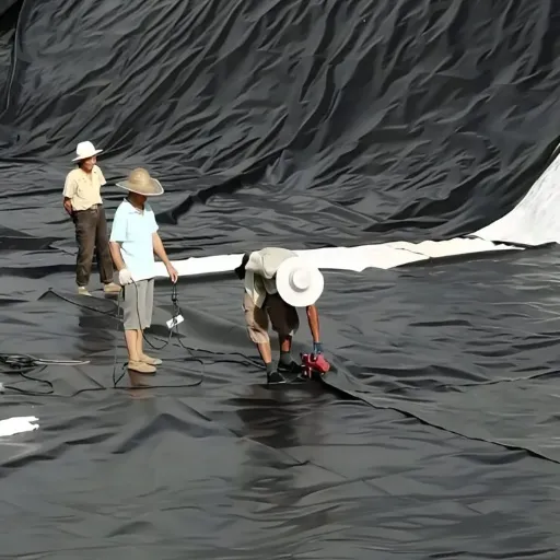
Where a regulation applies, it sets the minimum. Where it doesn’t, engineering precedent is the best guide.
40 CFR 258.40 governs composite liners in municipal solid waste landfill units:
- The upper component must be a flexible membrane liner of at least 30 mil, or 0.75 mm.
- Where that membrane is HDPE it must be at least 60 mil, or 1.50 mm.
- The lower component must be at least two feet of compacted soil at no more than 1×10⁻⁷ cm/s.
- The leachate collection system must keep head below 30 cm.
Read the 30-mil figure carefully. It’s a thickness floor for a non-HDPE membrane in a composite system, not a statement that 0.75 mm LLDPE suits waste containment. The rule was written when the composite liner, not the membrane alone, was the barrier.
State programmes add requirements on top, and those govern the permit. The same floor appears in 40 CFR 257.70 for coal combustion residual units.
Final cover is different again. 40 CFR 258.60 specifies an 18-inch infiltration layer and a 6-inch erosion layer with no membrane thickness figure at all, so cover gauge is a design decision. The landfill liner systems guide covers how those layers stack, and LLDPE geomembrane landfill covers the cap case.
The USDA Natural Resources Conservation Service published pond sealing standard 521A with explicit membrane minimums. The archived Oklahoma version from December 2007 lists LLDPE at 40 mil for wastewater and 20 mil for clear water. The Michigan version from 2013 lists 40 mil and 30 mil for the same two cases.
Two state standards, six years apart, disagree by 10 mil on the same question. That disagreement is the lesson: the governing document for your state decides, not a blog table.
The most specific guidance for LLDPE is Engineering New Zealand’s Practice Note 21. Table 2.2 recommends 1.50 mm LLDPE for ponds and 1.00 mm for factory-welded tanks, on the reasoning that factory seams carry less risk than field seams. The note also warns that nominal thickness isn’t actual thickness, and recommends seeking a 20-year product warranty plus a 5-year installation warranty, in writing.
How to Write Thickness Into a Specification
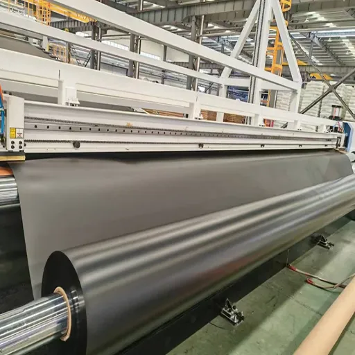
A thickness clause that survives procurement has five parts: the gauge, the surface, the tolerance basis, the standard, and the test that proves it.
- Nominal gauge in millimetres, with the mil equivalent in brackets.
- Surface: smooth or textured, stated separately for base and slopes if they differ.
- Tolerance basis: minimum average, plus the lowest individual reading permitted. For textured sheet, add the core thickness definition.
- Standard: GRI-GM17, with the revision year.
- Verification: thickness by ASTM D5199 on smooth sheet or D5994 on textured, tested per roll, with certificates at shipment.
A clause reading “1.5 mm LLDPE geomembrane to GRI-GM17, textured on slopes, minimum average core thickness 1.425 mm, no individual core reading below 1.35 mm, certificates per roll” can’t be satisfied by a 1.29 mm sheet. State the property too: puncture resistance of 370 N minimum average at 1.50 mm smooth, or 300 N at 1.50 mm textured, by ASTM D4833.
Have a thickness clause to check? Send the draft specification and the site conditions. We’ll mark it against GM17 line by line before it goes to tender. Send the design head and subgrade report.
Frequently Asked Questions
What thickness of LLDPE geomembrane do I need for a pond?
For an exposed farm or irrigation pond, 1.50 mm is the established figure, and 1.00 mm is common for protected installations and factory-welded tanks. Ponds under 1 m deep with a prepared, cushioned base can use 0.75 mm. Depth alone shouldn’t set the gauge; subgrade condition and exposure matter more.
Is 1.5 mm the same as 60 mil?
Yes, to within rounding. One mil is 0.0254 mm, so 60 mil is 1.524 mm and the trade calls it 1.5 mm. Both names refer to nominal thickness, so the delivered sheet may measure less under the GM17 tolerance for its surface.
What is the minimum thickness for a landfill liner?
In the United States, 40 CFR 258.40 requires at least 30 mil (0.75 mm) for the flexible membrane component of a composite liner, and at least 60 mil (1.50 mm) where the membrane is HDPE. State programmes commonly require more, and the permit governs. Most MSW base liners are specified at 1.50 mm or thicker.
Does thicker LLDPE mean a longer service life?
Not by itself. Thickness buys puncture and tensile margin, which extends life where mechanical damage is the risk. Where the risk is UV, thermal cycling or chemical attack, the resin, the antioxidant package and the installation detail decide.
Conclusion
LLDPE geomembrane thickness is a specification decision before it’s a purchase decision. GM17 gives eight gauges from 0.50 mm to 3.00 mm, property values that scale almost linearly, and a tolerance that differs between smooth and textured sheet.
Three habits keep the decision sound. Pick the gauge from load, exposure, chemistry and geometry rather than a depth rule. Write the tolerance basis and the property that matters into the order. Compare quotes at delivered thickness, not nominal.
The LLDPE geomembrane guide takes material selection further, and the LLDPE pond liner page covers the pond case.
A liner that meets its specification at the lowest installed cost is the cheap one. A liner 20% thinner than the specification isn’t a saving; it’s a different project.
Ready to fix the gauge? Send the application, the design head, the subgrade condition and any permit clause. We’ll return a thickness recommendation, the GM17 values behind it, and the clause wording for the order. Request a technical quote.